Room-wrapping configuration, Zig zag configuration – Edge Lighting TruLine .5A, 24VDC - Plaster-In LED System User Manual
Page 2
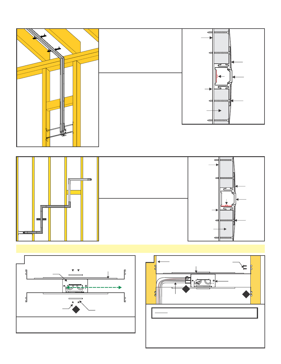
Section Two: Standard Horizontal Installation
A
JUNCTION
BOX
1
MOUNTING
BRACKET
PHILLIPS
SCREW
ADJUSTABLE
MOUNTING BAR
1: Mount each adjustable mounting bar to one side of the
junction box and secure them with the mounting brackets
and two Phillips screws provided.
2: Place the lips on the adjustable mounting bars against
the studs. Secure the adjustable bars to the studs with
the eight #8 screws.
3: Install conduit (if required by local electrial code) and run
low-voltage power wires to the junction box.
B
NOTE:
The adjustable mounting bars mount to studs that
are spaced 13" to 24" apart.
2
INSTALLATION
DIRECTION
ADJUSTABLE
MOUNTING BAR
STUD
#8 SCREW
2
3
JUNCTION
BOX
CONDUIT W/
LOW-VOLTAGE WIRES
Room-Wrapping Configuration
Room-wrapping configurations are used
for installations that join runs of TruLine
.5A on multiple planes (like a ceiling and a
wall) using miter-cut linear sections of
channel.
For room-wrapping installations, the LED
strip will be installed in the bottom of the
channel.
Zig Zag Configuration
Zig Zag configurations are used for
installations that join runs of TruLine .5A on a
single plane (like a ceiling or a wall) using
sections of channel joined by L connections.
For Zig Zag installations, the LED strip will be
installed in the side of the channel to allow the
strip to follow the channel corners.
LENS
PLASTER
MOUNTING
STRAP
CHANNEL
DRYWALL
DRYWALL
SCREW
LED
STRIP
LENS
PLASTER
MOUNTING
STRAP
CHANNEL
DRYWALL
DRYWALL
SCREW
LED
STRIP