Edge Lighting TruLine .5A, 24VDC - Plaster-In LED System User Manual
Page 14
14
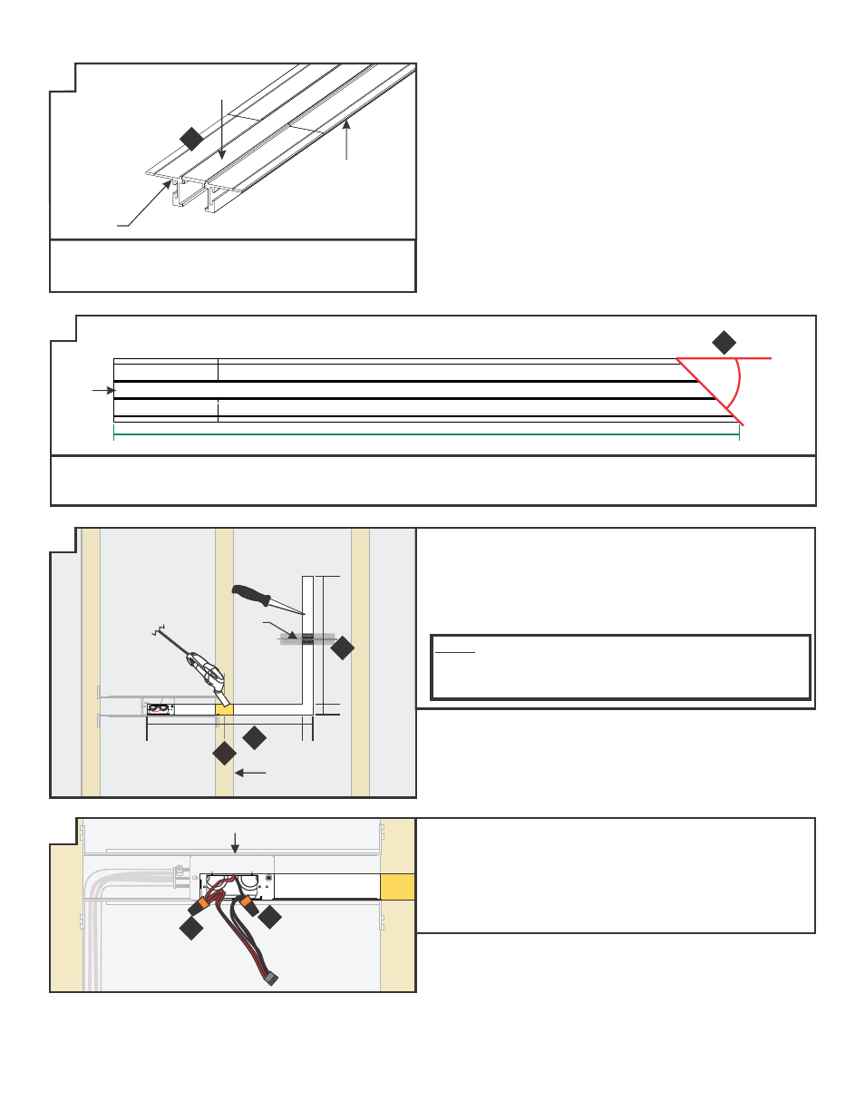
CHANNEL
TRAP DOOR
FRAME
LENS
7: Snap the lens into the assembled trap door frame and
channel BEFORE cutting to length. This ensures a proper
fit after installation.
45°
TRAP DOOR
FRAME
CHANNEL
SECTION
LENS
DESIRED LIT LENGTH
8: Determine the channel length and cut channel and lens at a 45° angle from the outer corner.
9: Cut additional lens/channel assembly for the opposing 45° angle and any other corners as required for the installation.
10: Measure and mark installation length, allowing for 0.75"
extra space at junction box for power end cap and 1.0" inch
at the end of the installation for the take-up box. Cut
out marked areas using appropriate tools.
11: Mark the location of the studs to the drywall for future
reference.
NOTE: To install channel vertically or in a wall without standard-
spaced studs, install perforated mounting straps every 32"
behind drywall and secure using two drywall screws. Mark the
location of any mounting straps to the drywall.
MARKING
STUD
1.05"
11
10
Z24
1.05"
12: Connect the red power supply (24VDC+) wire to the red
power connector wires with a wire nut.
13: Connect the black power supply (24VDC-) wire to the black
power connector wires with a wire nut.
14: Place the wire nut connections inside junction box.
JUNCTION BOX
13
Z22
Z23
Z25
7
8
10
12