Edge Lighting TruLine .5A, 24VDC - Plaster-In LED System User Manual
Page 15
15
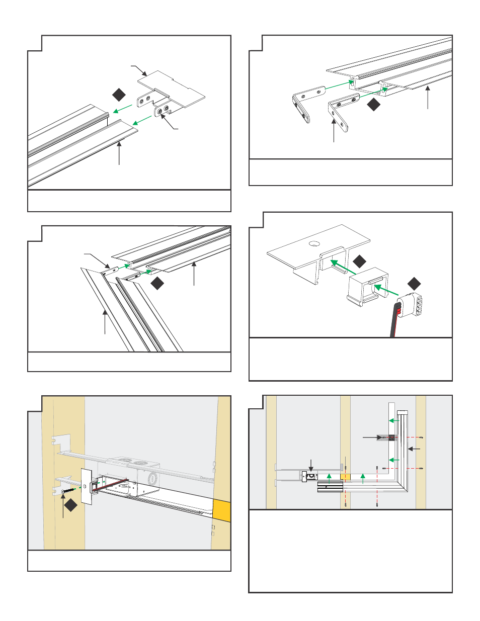
16: Insert the 90° joiner bracket halfway into the mitered
channel corner. Tighten the two M4 set screws on each
joiner bar with a 1.5MM Allen wrench.
16
Z27
TAKE-UP
BOX
CHANNEL
15: Slide the take-up box onto the non-power channel end and
tighten the M4 set screws with a 1.5MM Allen wrench.
17: Slide the other section of mitered channel onto the 90°
joining brackets and tighten the remaining M4 set screws.
17
90° JOINING
BRACKET
CHANNEL
CHANNEL
Z28
18: Rotate the connector and bend power connection wires
to place the power connector into the end cap insert.
19: Slide the assembled end cap insert and power connector
into the end cap.
18
20: Secure the assembled power connector end cap to the
junction box with the #4-40 screw.
#6 SCREW
CHANNEL
TRAP DOOR
21: Using the mark locations on the drywall, carefully make
a hole to channel using the provided square drill with
counter sink bit.
22: Secure the channel to the studs/mounting straps through
the drywall with the #6 screws using the provided square
recess bit.
23: Secure the Trap Door frame to the junction box with the
#4-40 screw.
Z26
M4 SET
SCREWS
Z29
19
15
90° JOINER
BRACKET
CHANNEL
#4-40
SCREW
20
Z30
Z31