Drucker Diagnostics Paralens Advance User Manual
Page 9
2.3 SETUP PROCEDURES (continued)
2.3.2 Electrical Connections
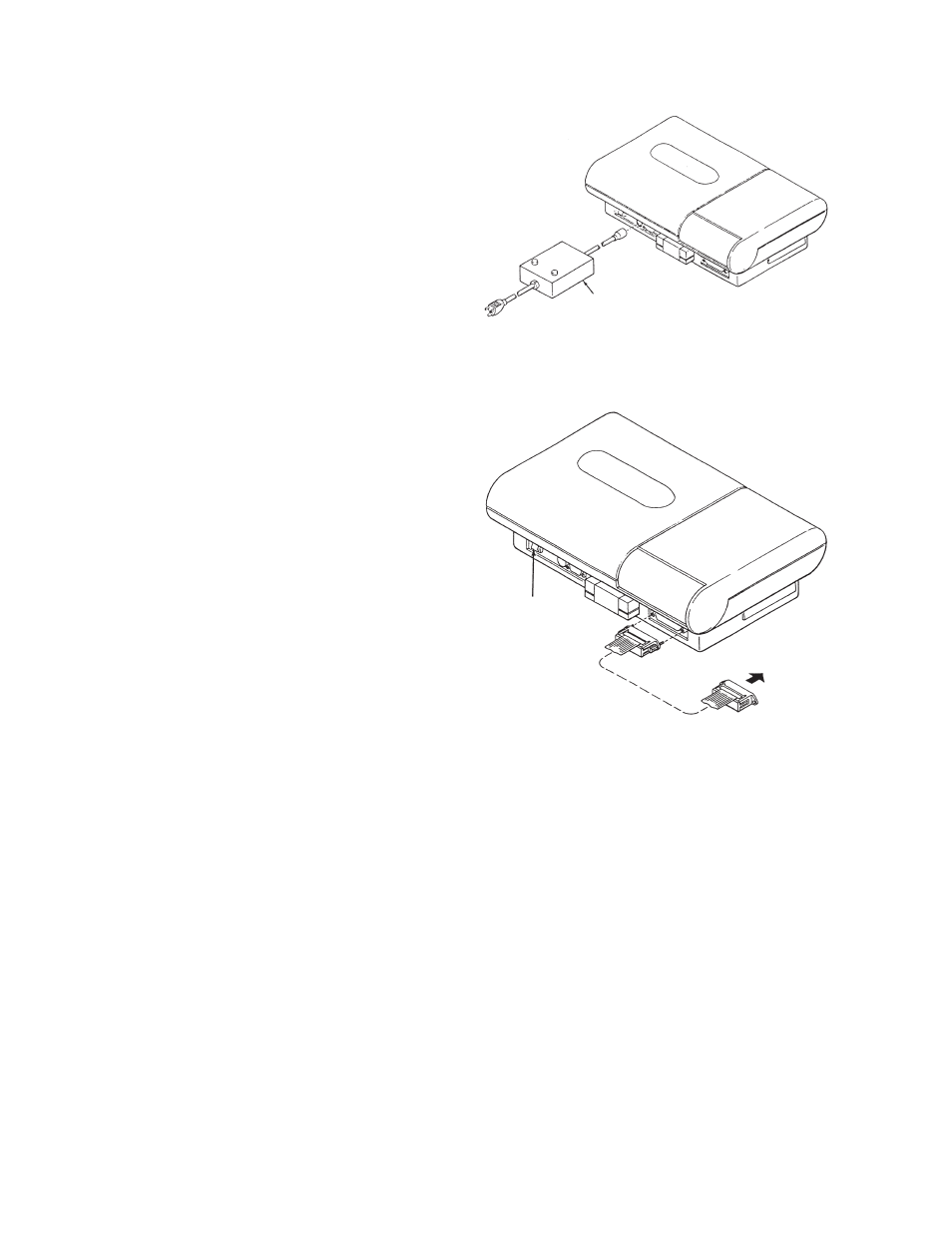
• Analyzer-to-Power Pack
Referring to Figure 2-2, insert the 8-pin plug
of the power pack into the POWER PACK
CONNECTOR in the back of the Autoread Plus
analyzer.
Before plugging the line cord of the power pack
into an electrical receptacle, see the electrical
requirements specified on the data plate and in
Section 2.3.4.
• Analyzer-to-Printer
(Note: For analyzers with USB printers, consult
the included insert labeled “IMPORTANT
INFORMATION”.)
In order to connect the printer, the cable
assembly supplied with the System must be
installed between the Autoread Plus analyzer
output port and the printer. Referring to Figure
2-3, attach the cable as follows:
a) Insert the 25-pin plug of the cable assembly
into the PRINTER connector in the back
panel of the analyzer.
b) Secure the plug to the connector by manually
tightening the knurled captive screws into the
sockets of the connector. Note: the captive
screws are slotted and can be tightened with
a screwdriver.
c) Plug the unattached connector of the cable
into the jack on the printer.
See the manufacturer’s manual furnished
with the printer for instructions on attaching
accessories.
2.3.3 QBC Capillary Centrifuge
Consult the separate manual supplied with the QBC
Capillary Centrifuge for detailed setup instructions,
power requirements, and operating directions.
Figure 2-2.
Power Connection Diagram
Figure 2-3.
Printer Cable Connection
2-2
POWER PACK
POWER SWITCH
TO PRINTER