Drucker Diagnostics Paralens Advance User Manual
Page 19
3.1.4 Transport Mechanism (continued)
Inserting a QBC tube and closing the platform door
initiates the following start sequence:
• An optical sensor detects that the tube is
inserted, thereby activating a switch.
• As the door is shut, an actuating bar on the
underside of the door closes a mechanical
switch to enable the transport start sequence.
• A motor moves the transport carriage with
collet to clamp the unsealed end of the tube
firmly in position.
• Once the tube is colleted, the transport carriage
moves away from the loading platform into the
optics chamber.
The test sequence for a patient specimen consists
of three phases:
• Identification scanning;
• Measurement scanning; and
• Data analysis.
Initially, the tube is subjected to forward and reverse
check scans while the optical sensors determine
the type of QBC tube float dimensions and plasma
volume. (NOTE: Every scan – regardless of the
test mode – is accompanied by a muted whirring
sound caused by rapid acceleration of the motor
and tube transport mechanism; this whirring sound
is normal.) The tube then undergoes a series of rapid
measure ment scans as described in paragraph
3.1.7. When scanning is complete, the specimen
tube is returned to the loading platform while the
analysis and data reduction phase continues. Total
test time is between 1 and 3 minutes depending on
the software version and the test being performed.
The transport mechanism, lead screw, and guide
rod are lubricated for the life of the instrument.
Should breakage ever occur during tube insertion
or colleting, a removable waste tray below the
loading platform is provided to collect specimen
and glass (Figure 3-8).
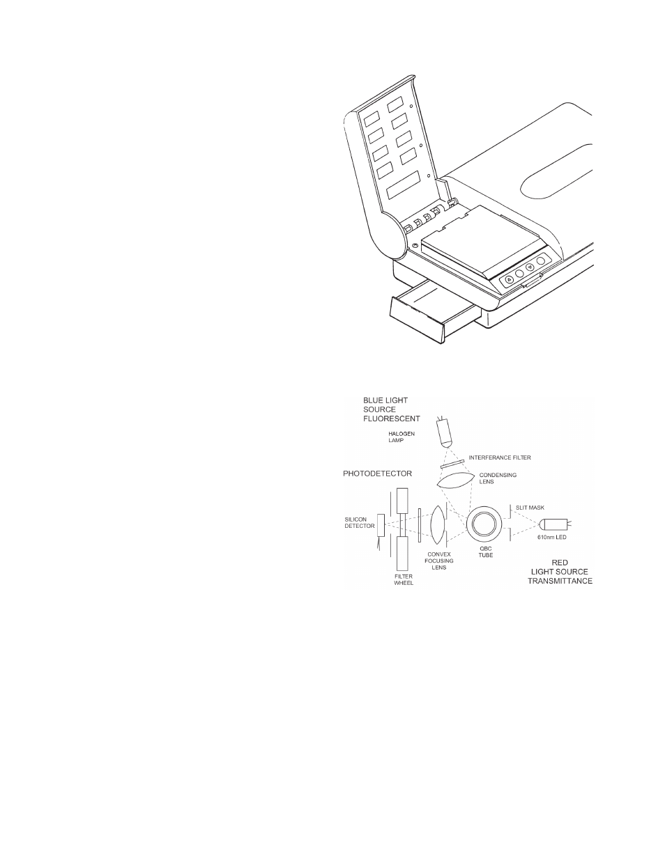
3.1.5 Optics
The optics system, shown schematically in
Figure 3-9, consists of three basic sections:
• Red light source, for transmittance scans.
• Blue light source, for fluorescence scans.
• Photodetector with associated focusing lens
and filters.
3-4
Figure 3-8.
Waste Tray Shown Partially Open
WASTE TRAY
Figure 3-9.
Optics System Schematic