Update underside weldments, Configure implement, Tack rear bottom gussets – Great Plains 2007HD Update Installation User Manual
Page 9: Lh rear bottom gussets, Fb d u
05/25/2011
166-370M
Great Plains Manufacturing, Inc.
5
Update Underside Weldments
Refer to Figure 2
Gussets, nut blocks and a box plate are added to the
underside of the wing pivot extensions (4
,
locations,
two on each wing). This work is considerably easier with
the implement folded, and needs to be done prior to
cart-implement separation.
Configure Implement
3.
Raise, fold and configure as if for transport (lift locks
and wing fold locks installed). Set all hydraulic
remotes to Float to relieve pressure in lines.
4.
Disconnect all harnesses and cables at cart hitch.
5.
Take steps to protect hoses and cables near weld
regions. Cover with welding blankets, or temporarily
remove, as needed.
Tack Rear Bottom Gussets
LH Rear Bottom Gussets
Start with the left (LH) side. The left and right side new
parts are not identical, although they are similar and
install in mirror-image locations.
Crushing Hazard:
Remove only the underside bolts. Do not remove the
cross-bolts or the top side bolts. Removing all the fasteners at
a joint could allow a dangerous joint separation resulting in
serious injury or death, and extensive machine damage.
Refer to Figure 2
6.
At the Back wing pivot extension joint
, remove
two sets:
804-023C WASHER LOCK SPRING 3/4 PLT
802-910C RHSNB 3/4-10 X 2 GR5 PLT
Save the washer
. The nut
not re-used.
Refer to Figure 3
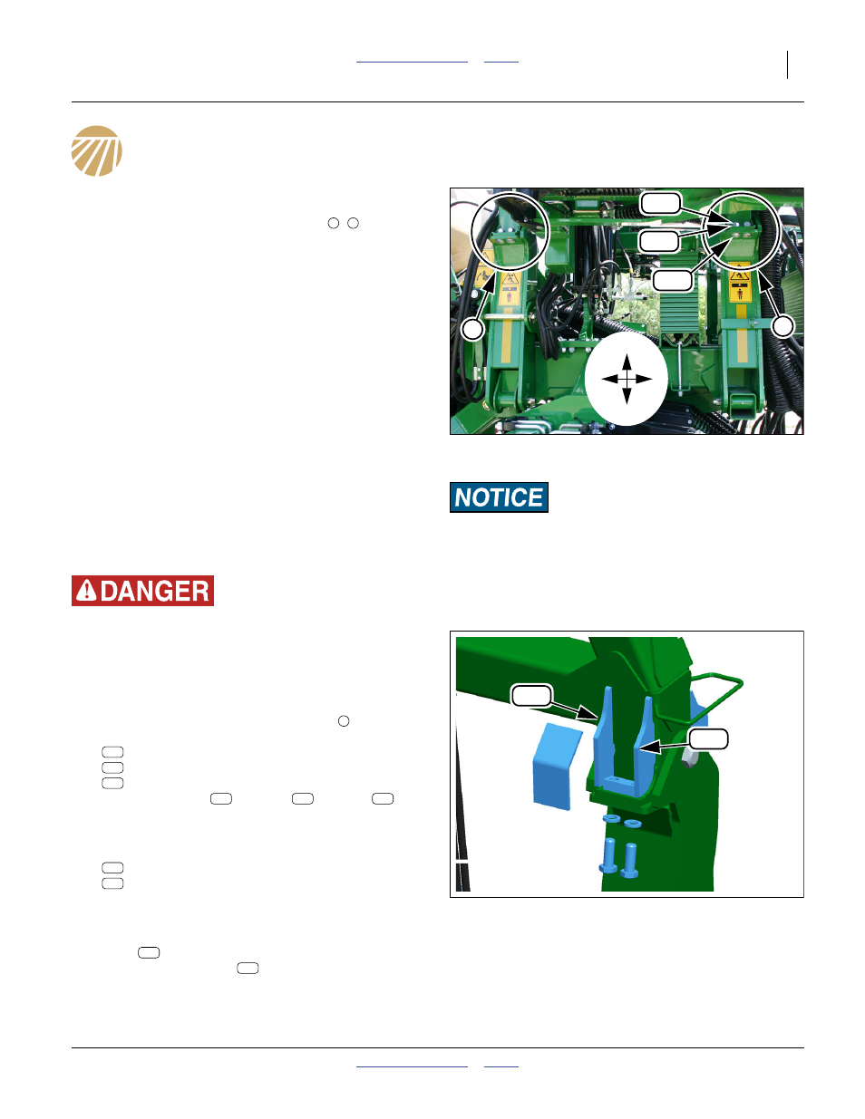
7.
Select one each new:
160-804D FRAME EXT BOT GUSSET LH REWORK
160-805D FRAME EXT BOT GUSSET
REWORK
Hold these in their intended positions. Mark paint for
removal.
8.
Remove paint. Tack weld gusset plates in position.
Plate
is to implement front, against the existing
smaller gusset. Plate
is to implement rear,
against the existing smaller gusset. Place both as
close to the joint and up against the wing as allowed
by pre-existing weld fillets.
Equipment Damage Risk:
Disconnect all electrical connections between cart and tractor
prior to welding. Welding can induce high voltages and/or
high current flows that could damage sensors, WSMB and
WSMTs on the cart or implement.
Figure 2
Underside Work Locations
Q0113
F
B
D
U
F
B
B
F
Figure 3
LH Rear Underside Gussets
Q0120
908
909
B
908
909
908
909