Install front gussets, Install right front gusset, Install left front gusset – Great Plains 2007HD Update Installation User Manual
Page 27
Great Plains Manufacturing, Inc.
Update Cart
23
05/25/2011
166-370M
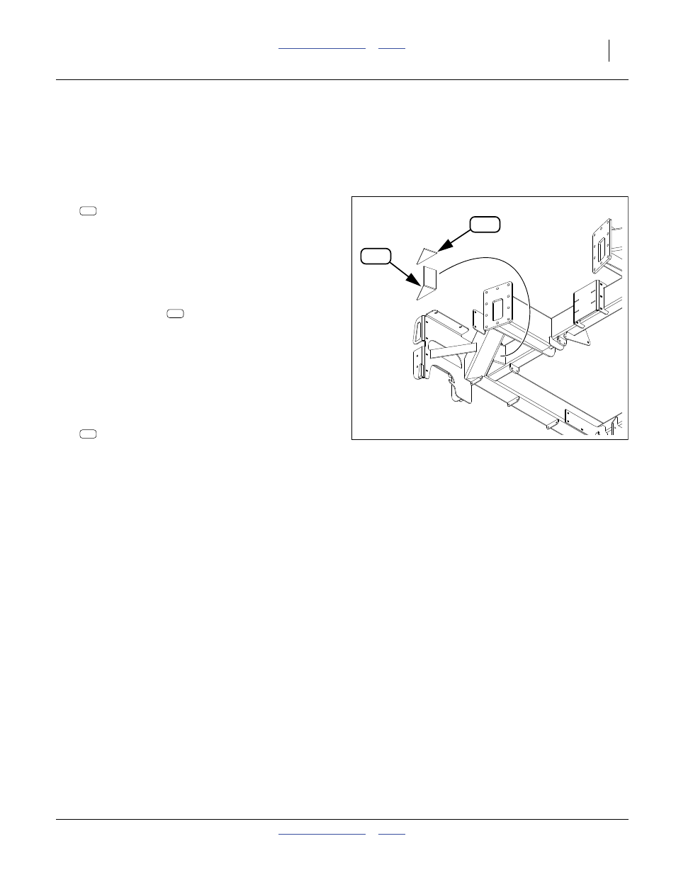
Install Front Gussets
Install Right Front Gusset
115. Remove the front reflector panels (if any) and walk-
board to provide access.
Refer to Figure 36
116. Select one new:
266-309D FRNT MAIN FRAME CRNR CAP PLT
Note: Despite the “
CAP
” descriptor, this part is used as
the base of the new gusset structure.
117. Position this plate in the outer crevice of the front
outside tool bars. Mark the weld region along the
edges. Remove paint on the tubes in the weld
regions.
118. Position the plate
fully into the crevice, with the
bottom triangle about 6 cm (
1
⁄
4
in) higher than the
bottom faces of the tube, and parallel with the tube
bottom faces. Tack weld in position.
119. Finish weld all around (inside and out), except near
the tip of the triangle (leave the tip unwelded to pro-
vide a weep/breather opening). Use at least a 6 cm
(
1
⁄
4
in) fillet.
120. Select one new:
266-308D FRONT MAIN FRAME CORNER GUSSET
121. Position this gusset at the top of the plate just
installed, fully into the crevice, and parallel to the top
of the adjacent tubes. Tack weld in position.
122. Finish weld all around.
Install Left Front Gusset
123. Repeat step 116 through step 122 for the left side.
124. Remove all slag and splatter. Clean and de-grease
all bare and discolored areas. Paint green.
Note: To ease access to fan hydraulics, walkboard
re-installation is deferred until step 184 on
page 32.
Figure 36
Right Front Gusset (from below)
32126
927
926
927
927
926