Update wing pivot anti-rotation – Great Plains 2007HD Update Installation User Manual
Page 42
38
NTA607HD or NTA2007HD
Great Plains Manufacturing, Inc.
166-370M
05/25/2011
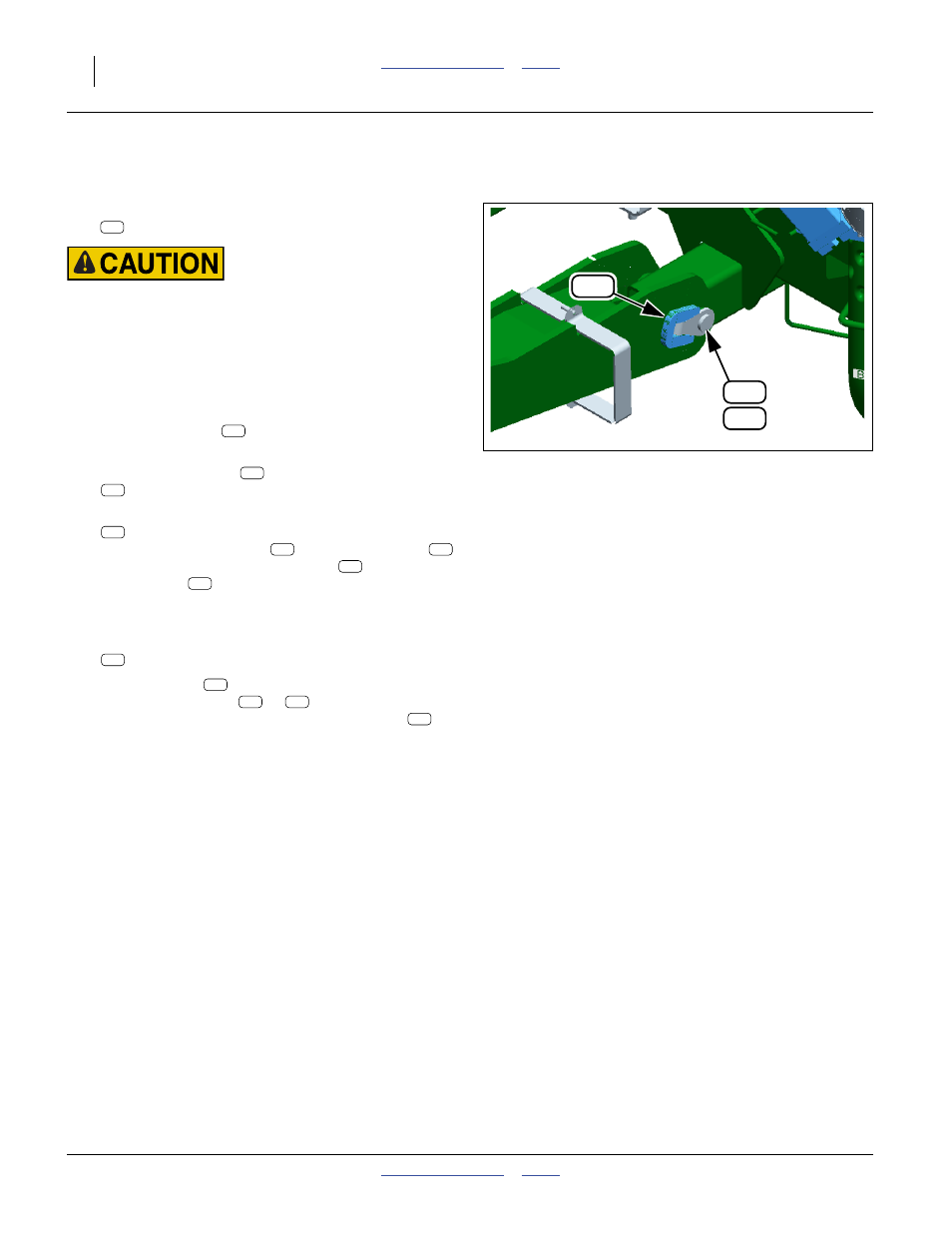
Update Wing Pivot Anti-Rotation
Refer to Figure 63
If the existing pins are undamaged, leave the wing pivot
pins
in place for this update.
Pinch / Crush Hazard:
If the existing pins must be removed, follow instructions care-
fully. Remove only one pin at a time. Begin inserting a second
pin before the first is fully removed. Without use of additional
hoists and supports, an un-pinned wing can move or fall,
which could result in injury and equipment damage.
Start with the LH rear pivot.
220. If the existing pin
is undamaged, continue at
221. At the damaged pin
, remove and save one:
805-255C PIN ROLL 3/8 X 2 1/2 PLT
222. Select two new:
160-201H WING PIVOT PIN WELDMENT
Use one of the new pins
to drive the old pin
out. Then use the second new pin
to drive the
first new pin
back out, with this second new pin
replacing the damaged old pin as originally
installed.
223. Select one new:
160-811D WING HINGE PIN ROTATION STOP
224. Place the stop
around the pivot shaft cap of the
new or existing pin (
or
). On the pivot exten-
sion, mark around the outer edge of the stop
for
paint removal. Remove paint in preparation for
welding.
225. Tack weld the stop, at the outer edges only.
226. Finish weld the stop, fillet of 7 mm (
1
⁄
4
in.) fillet.
227. Clean off all weld splatter and slag. Allow the welds
to cool. Paint green.
228. Repeat step 220 through step 227 for the LH front,
and RH wing pivot pins.
Figure 63
Wing Pivot Anti-Rotation
Q0124
104
915
901
104
104
104
200
901
901
104
901
901
915
915
901
104
915