Install row harnesses, Connector id – Great Plains 2007HD Update Installation User Manual
Page 49
Great Plains Manufacturing, Inc.
Update Harness
45
05/25/2011
166-370M
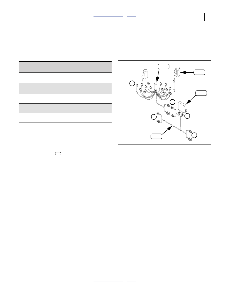
Install Row Harnesses
Refer to Figure 77, Figure 78 (which is part of the full
harness diagram found on page 88 and 89)
Connector ID
Harness connections are shaped, sized, polarized,
keyed and color-coded to prevent mis-configuration.
Each WSMB harness has eight connectors, which can
be confusing. Familiarity can save time.
These instructions have you install and completely con-
nect one row harness
at a time. Row harness leads
are labelled 1-16 on every harness. Having multiple
leads with the same numbers nearby can lead to mis-con-
nection.
Group
Type (on
Cable)
Function
4-pin plug
6-pin
a
plug
a. Not all pin locations may be populated.
Upstream CANbus power
Upstream CANbus data
4-pin receptacle
6-pin
a
receptacle
Downstream CANbus power
Downstream CANbus data
dual 12-pin
receptacle
WSMB
dual 12-pin
plug
Local function
(sensor harness in this case)
3-pin
Connection to each
blockage sensor
Figure 77
WSMB and Row Harness
32149
a
b
c
d
e