Re-hitch implement, Install front pull link, Re-connect lift link – Great Plains 2007HD Update Installation User Manual
Page 61
05/25/2011
166-370M
Great Plains Manufacturing, Inc.
57
Re-Hitch Implement
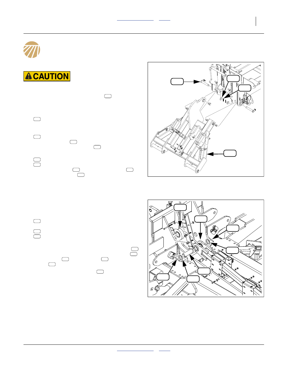
Install Front Pull Link
Pinch / Crush Hazards:
Use an adequate hoist or lifter. Use three or more lines. Place
lines where they cannot slip. The weldment
weighs over
270 kg (600 pounds).
Refer to Figure 91
331. Select one new:
160-315H NTA607HD FRONT PULL LINK WLDMT
Attach a hoist.
332. Select two saved:
160-201H WING PIVOT PIN WELDMENT
Hoist the pull link
into alignment with the imple-
ment main frame. Insert pins
.
333. Select two sets saved:
804-039C WASHER FLAT 1 1/4 SAE PLT
805-255C PIN ROLL 3/8 X 2 1/2 PLT
Place the washers
on the weldment pins
.
Secure with poll pins
. Leave the hoist attached
to the pull link.
Re-Connect Lift Link
Refer to Figure 92
334. Select one saved:
160-781D PIN 1 1/2 X 4 USABLE 1045
with its two sets of:
804-117C WASHER FLAT 1/4 HARD ASTMF436
805-117C PIN ROLL 1/4 X 2 1/2 PLT
Remove one washer and roll pin.
335. Use the hoist to bring the top lug of the pull link
into alignment with the front clevis of the lift link
.
Insert the pin
. Add a washer
. Secure with
roll pin
.
336. Check the length of the lift link
. Adjust the rear
clevis turnbuckle as needed to obtain a length,
clevis center-line to clevis center-line of:
202.0 cm (79
17
⁄
32
in)
Note: Although the hoist could be disconnected from the
pull link at this time, it may be useful for implement-
cart hitching.
Figure 91
Install New Front Pull Link
31238
902
193
104
200
902
902
104
902
104
193
200
193
104
200
Figure 92
Connect Lift-Assist Link
31423
112
902
196
194
118
194
196
118
194
196
902
112
118
194
196
112