Servicing the at30, Troubleshooting chart – Exide Technologies Section 94.40 User Manual
Page 53
SERVICING THE AT30
49
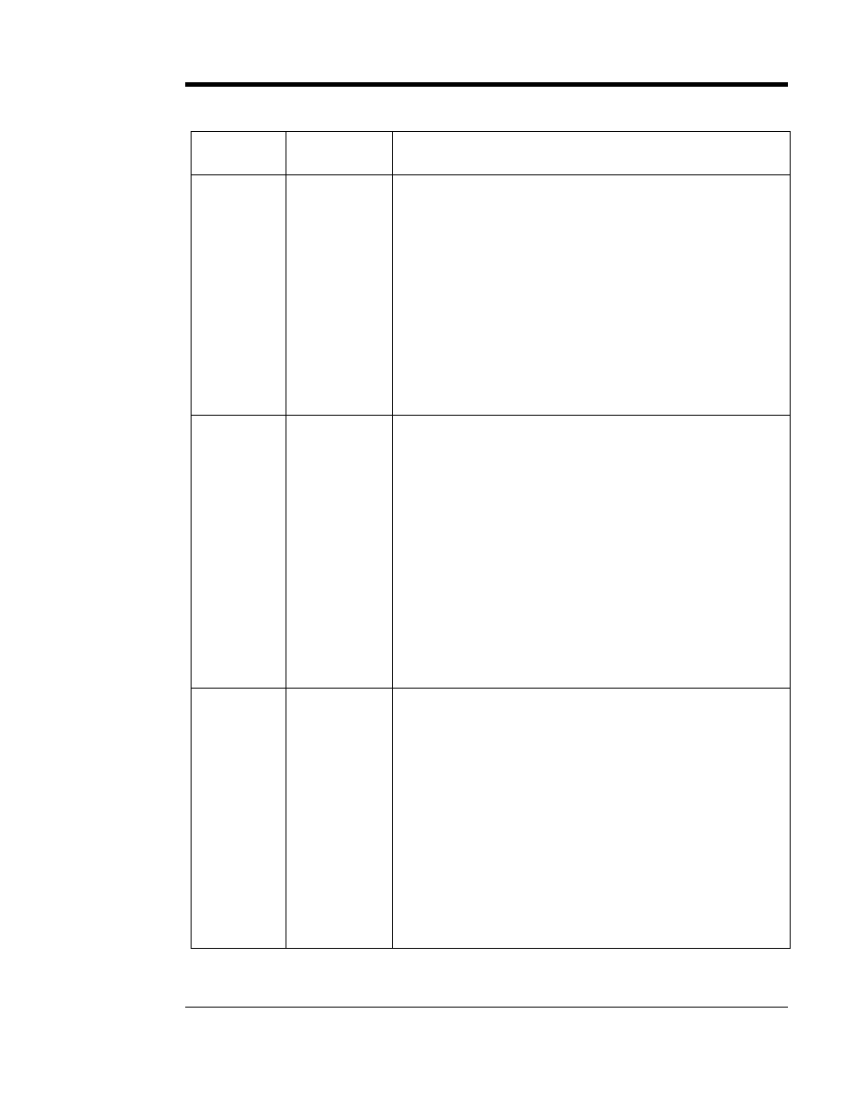
3.4. TROUBLESHOOTING CHART
SYMPTOM PROBABLE
CAUSE
RECOMMENDED ACTION
Front panel
meter
displays all
segments
“On” or all
segments
“Off.” Charger
may have no
output.
1. An external
surge has
interrupted
operation of the
microprocessor
or the display
controller.
1A. Soft Reset of control board by pressing S7 reset switch.
S7 is located inside the charger, on the control board’s right
edge (as viewed from the rear of the front panel). This will
restart the control board without modifying any settings.
1B. Hard Reset of control board by pressing and holding the
“UP” button on the front panel, and simultaneously pressing
S7 reset switch. This will restart the control board and restore
all settings to factory default. Reset parameters per Section
2.3 of this manual.
1C. Remove all power from the AT30 to allow control board to
discharge all voltages. This can be done by opening the AC
circuit breaker and disconnecting the control board plug(s).
Keep power removed for approximately 5 minutes to allow
voltages to discharge.
AC breaker
trips (or fuses
clear)
immediately
1. Shorted
rectifier diode
or SCR
2. Defective
wiring to T1 or
to rectifier
bridge
3. Defective
transformer T1
1. Test by disconnecting wires #
7, 8 & 9 at the rectifier
module(s) (A16) mounted on the main heat sink(s), or at the
main transformer (T1). Measure resistance between the ac
terminals (bottom terminals) on the rectifier module(s). It
should be at least 100,000 Ohms (check both polarities). If
resistance is low in either direction, replace the rectifier
module(s) (A16) as needed.
2. Check spacing of terminals and check wiring for signs of
insulation damage, burns, etc. Repair as necessary.
3. Test by disconnecting wires #
7, 8 & 9 from the transformer
secondary taps (T1-X1, X2 and X3). If ac breaker still trips,
test by disconnecting wires #
42, 43, 44, 45, 35 and 36 from
the tertiary taps (T1-Y0, Y1, Y2, Y3, W1 and W2). If ac breaker
still trips, replace the transformer (T1).
AC breaker
trips (or fuses
clear) after a
few minutes
1. Loose
connection to
breaker/fuse
2. Wrong ac
voltage, or T1
taps miswired
3. Open SCR
4. SCR not
controllable
1. Check and tighten connections as required.
2. Be sure the transformer primary taps (T1-H1, H2 and H3)
are wired correctly for your input voltage. See Section 1.6 for
details.
3. Use a clamp-on ammeter to measure the current in wires #
7, 8 & 9, between T1 and the rectifier modules. If it less than
50% of the dc output current, one of the six (6) SCRs or
diodes is defective. Replace the rectifier module(s) (A16).
4. Disconnect the wire harness plug from connector J26 on the
top of the Gate Driver pc board (A15) and restart the AT30. If
you are able to measure output current, one of the SCRs is
defective. Test and replace the rectifier module(s) (A16) as
needed.