Installing the at30 – Exide Technologies Section 94.40 User Manual
Page 15
INSTALLING THE AT30
11
PROCEDURE
1. Verify that all voltages within the AT30 are de-energized and locked out.
2. See Section 3.5 for necessary steps to follow when accessing internal
components within the AT30.
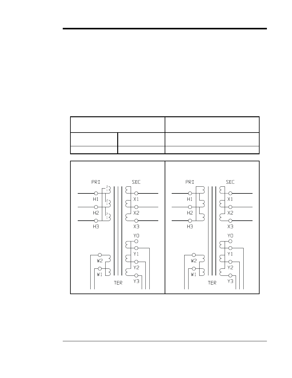
3. Change the jumpers on the transformer (T1) as shown in the table below.
4. Always use all three (3) jumpers.
5. Make sure all connections are tight.
6. Check your work before reenergizing the AT30.
7. For more information, see the schematics & wiring diagrams in Appendix C.
MAIN TRANSFORMER (T1) CONNECTION TABLE
TYPICAL TRANSFORMER (T1)
208/240 Vac - 60 Hz INPUT
TYPICAL TRANSFORMER (T1)
480 Vac - 60 Hz INPUT
208 Vac
jumper setting
240 Vac
jumper setting
jumper setting
H1, H2, H3 to 1
H1, H2, H3 to 2
none
SCHEMATIC
208/240 Vac - 60 Hz transformer (T1)
SCHEMATIC
480 Vac - 60 Hz transformer (T1)