Installing the at30 – Exide Technologies Section 94.40 User Manual
Page 21
INSTALLING THE AT30
17
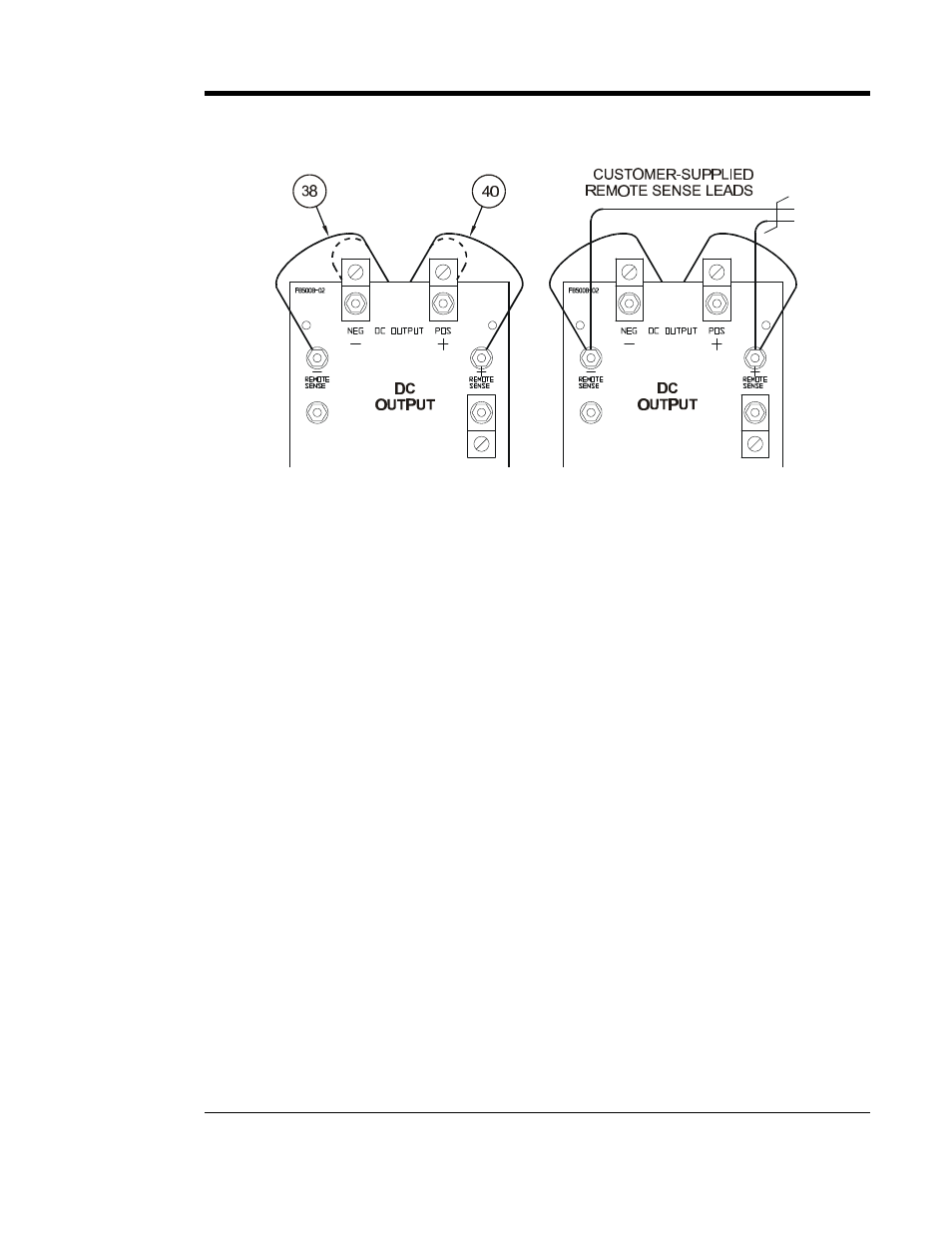
6. Connect user-supplied external remote sense leads from the battery or dc bus
to the remote sense terminals on the I/O panel.
7. Replace the two (2) dc output CU-AL compression lugs and tighten all
hardware.
8. Check your work thoroughly. Replace the safety shield (if supplied) before
reeneregizing the AT30.
9. Restart the AT30 according to the instructions in Section 2.1.
NOTES
1. Use #16 AWG twisted pair.
2. Maximum current is 150 mA.
3. Run leads in their own conduit.
4. Fuse the wiring at the battery or dc bus.
DISABLING REMOTE SENSE
If you ever need to disable remote sense, follow the steps below:
•
De-energize and lock out all ac and dc voltages to the AT30. Check with
a voltmeter.
•
Disconnect the remote sense wires from the battery or dc bus terminals
first.
CAUTION: You must do the steps above first.
•
Remove the remote sense leads from the remote sense (+) and (-)
terminals on the I/O panel. Insulate each lead separately. Coil up the
wires and leave them in the bottom of the charger, in case you want to
wire for remote sense again in the future.
•
Reconnect wire # 40 to the dc output (+) terminal.
•
Reconnect wire # 38 to the dc output (-) terminal.
•
Restart the AT30 according to the instructions in Section 2.1.