Servicing the at10.1 – Exide Technologies Section 94.30 User Manual
Page 65
SERVICING THE AT10.1
61
Replacing the power (ballast) resistor (R3) - 48 and 130 Vdc units only
For 48 Vdc and 130 Vdc AT10.1s rated 30-100 Adc, resistor R3 is
mounted with metal brackets onto the back panel of the enclosure. Cut
wires # 49 and # 55, connected to R3, as close to the resistor leads as
possible. Strip off 0.25in / 6.4mm of insulation from the cut ends of the
wires. Unscrew the top mounting-bracket and remove the existing
resistor. Mount the new R3 resistor and replace the top mounting-bracket.
Carefully re-solder the cut wires to R3. Polarity is not important.
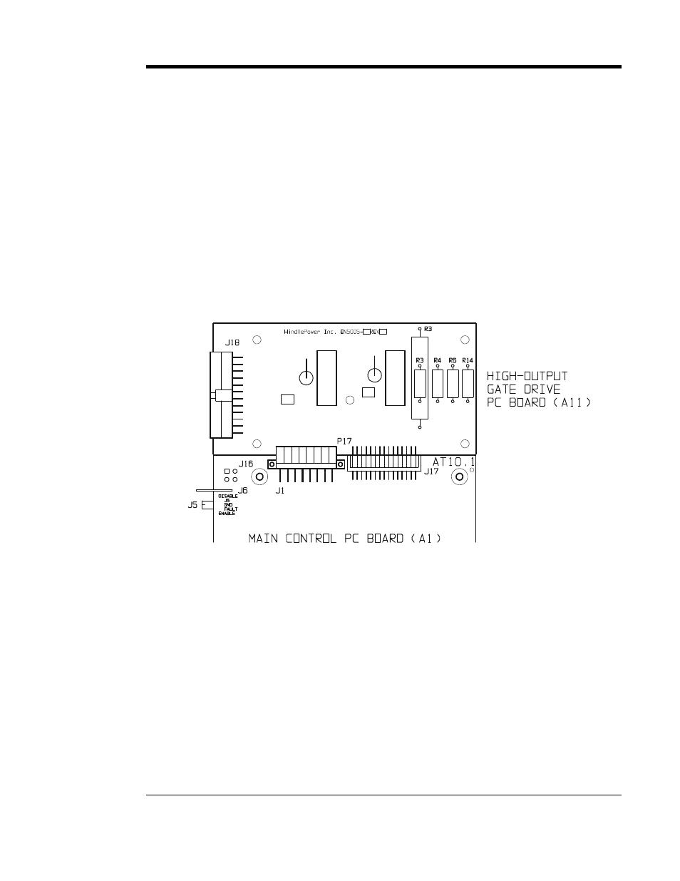
Replacing resistors (R3, R4, R6, R14) on the Gate Driver pc board (A11)
In all AT10.1s rated 30-100 Adc, resistors R4, R6 and R14 are soldered
directly onto the Gate Driver pc board (A11). In 12 Vdc and 24 Vdc
AT10.1s rated 30-100 Adc, R3 is also soldered directly onto A11. See
detail of the Gate Driver pc board (A11) below for proper location.
If any of these resistors need to be replaced we suggest you order a new
Gate Driver pc board (A11). See
Replacing the Main Control pc board
(A1) and/or Gate Driver pc board (A11) on page 59.
If any of these resistors
must be replaced without replacing A11, select the
proper part number listed in the table starting on page 62 and order it from
the factory or your sales representative.
Remove A11 as described on page 59. Using wire cutters, clip the
soldered leads of the old resistor and remove it from A11. Carefully
solder on the new resistor, making sure not to damage any other
components on A11. Polarity is not important for these resistors. Once
the solder cools, replace A11 as described on page 59.