Installing the at10.1, Main power transformer (t1) connection table – Exide Technologies Section 94.30 User Manual
Page 15
INSTALLING THE AT10.1
11
PROCEDURE
1. Verify that all voltages whithin the AT10.1 are de-energized and locked out.
2. See Section 3.5 for necessary steps to follow when accessing internal
components within the AT10.1.
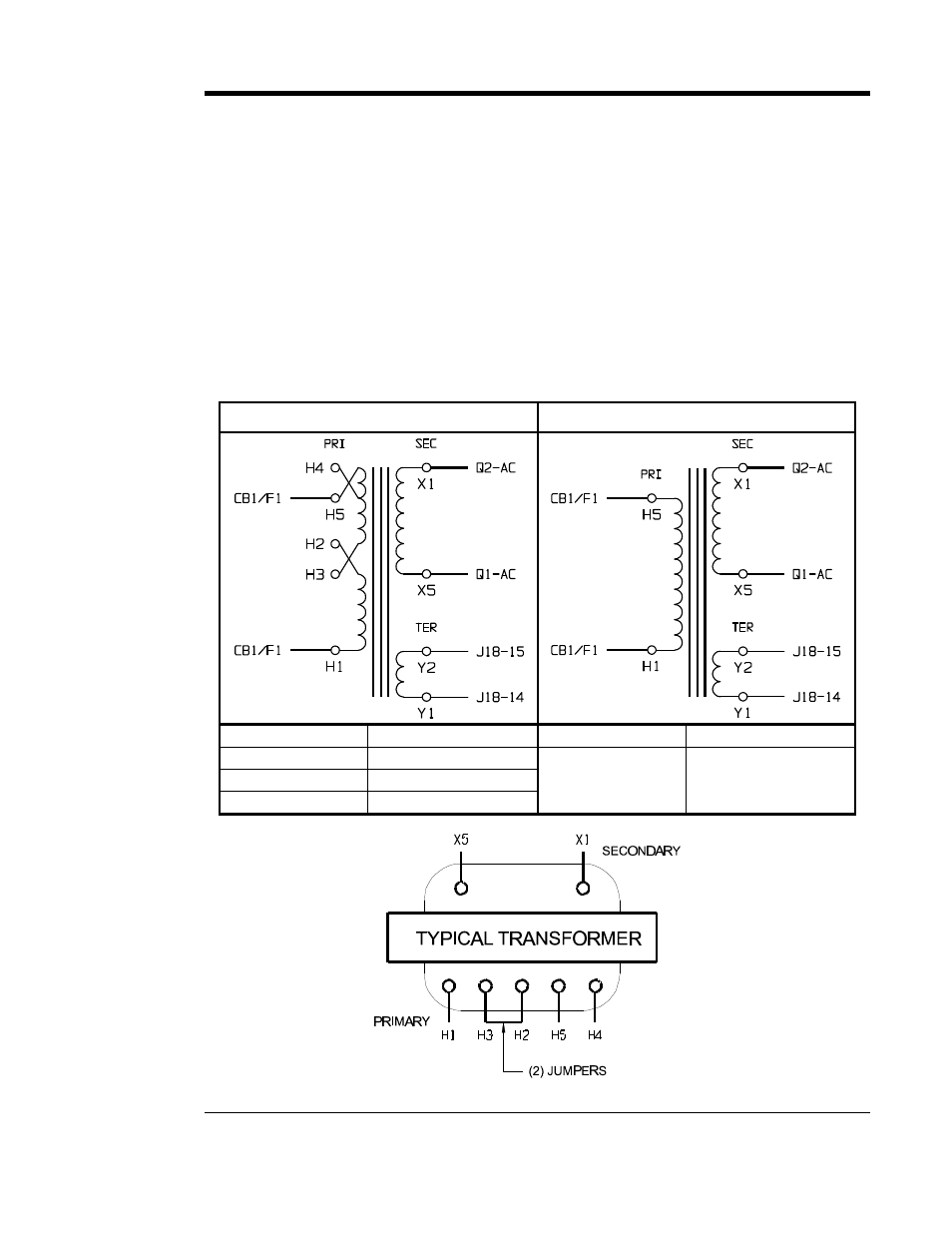
3. Change the jumpers on the transformer (T1) as shown in the table below.
4. If your transformer is supplied with two (2) jumpers, always use both as
specified in the table.
5. Make sure all connections are tight.
6. Check your work before re-energizing the AT10.1.
7. For more information, see the schematics & wiring diagrams in Appendix C.
MAIN POWER TRANSFORMER (T1) CONNECTION TABLE
120/208/240 Vac - 60Hz
480 Vac - 60 Hz
INPUT
JUMPERS
INPUT
JUMPERS
120 Vac - 60 Hz
H1-H3, H2-H5
208 Vac - 60 Hz
H2-H4 (2) JUMPERS
480 Vac - 60 Hz
NONE
240 Vac - 60 Hz
H2-H3 (2) JUMPERS