Installing the at10.1 – Exide Technologies Section 94.30 User Manual
Page 23
INSTALLING THE AT10.1
19
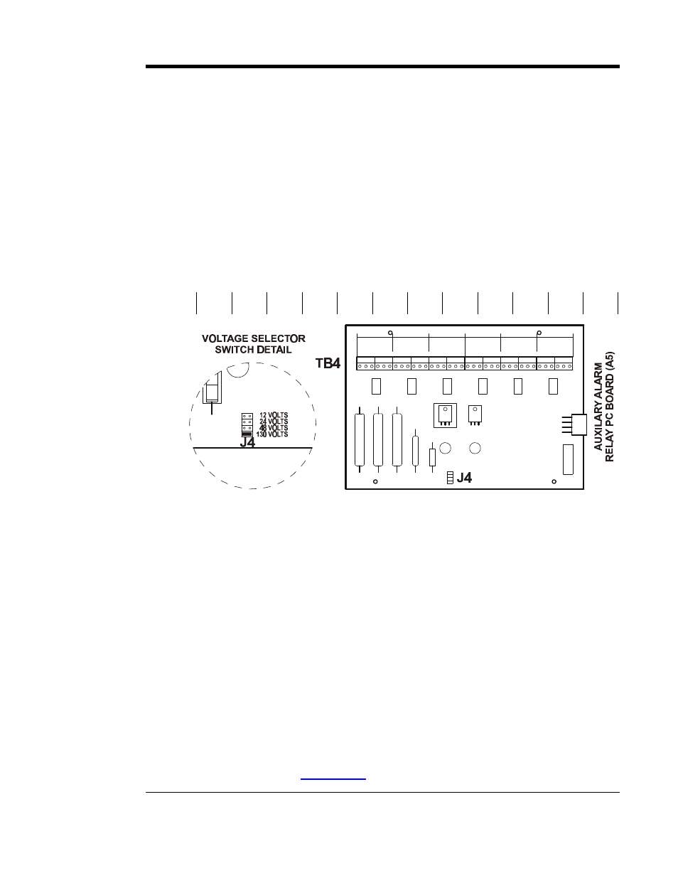
Auxiliary Relay Board (optional)
The optional Auxiliary Alarm Relay PC Board (A5), mounted on the right
side panel of the circuit breaker bracket, provides two (2) form-C contacts
(TB4-1 through TB4-36) for each of the following individual alarms:
•
High DC Voltage
•
Low DC Voltage
•
DC Output Failure
•
AC Input Failure
•
Ground Fault Detection (positive or negative)
•
Summary (common) Alarm
Alarm contacts (TB4) are as follows, shown in non-alarm condition:
HVDC
HVDC
LVDC
LVDC
DC OUT
FAILURE
DC OUT
FAILURE AC FAIL
AC FAIL
GROUND
DETECT
GROUND
DETECT SUMMARY SUMMARY
C, NC, NO C, NC, NO C, NC, NO C, NC, NO C, NC, NO C, NC, NO C, NC, NO C, NC, NO C, NC, NO C, NC, NO C, NC, NO C, NC, NO
1 2 3
4 5 6
7 8 9
10 11 12 13 14 15 16 17 18 19 20 21 22 23 24 25 26 27 28 29 30 31 32 33 34 35 36
PROCEDURE
1. Deenergize and lock out all ac and dc voltages to the AT10.1.
2. Allow internal voltages to dissipate, then check with a voltmeter.
3. Remove the plexiglas safety shield.
4. Route your remote annunciator wiring into the enclosure through one of the
unused conduit knockouts on the side of the enclosure.
5. Connect the wiring (use #22-14 AWG) to the appropriate terminals of TB4
on the Auxiliary Alarm Relay board (as shown in the figure above). Strip
each wire 0.25in / 6.4mm and securely tighten the terminal screws.
6. Replace the safety shield and restart the AT10.1.
NOTES
1. Alarm contacts are rated at 0.5A / 125 Vac or Vdc.
2. Terminal block (TB4) is compression type, accepting #22-14 AWG wire.
3. Terminals are labeled in non-alarm condition.
4. For a detailed view of the optional Auxiliary Alarm Relay PC Board (A5),
refer to drawing (
JE5030-29
) listed in Appenix C on Page 80.