Installing the at10.1 – Exide Technologies Section 94.30 User Manual
Page 12
INSTALLING THE AT10.1
8
1.5.3. Rack-Mounting the AT10.1
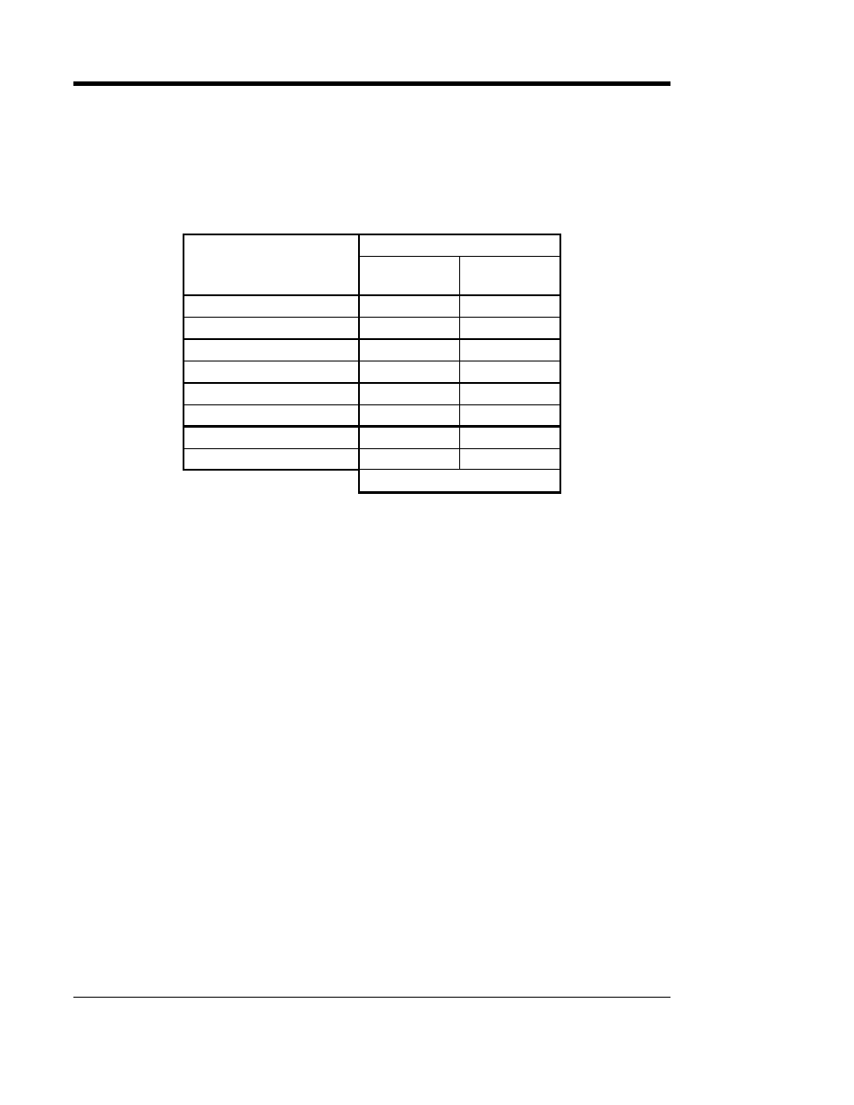
All ratings of the AT10.1 can be installed in most relay racks with
standard EIA hole spacing. A relay rack-mounting kit is required. For kit
availability see ordering information in Appendix B on page 71. Order the
appropriate rack mounting kit for your charger, as shown in the following
table.
RACK WIDTH
CHARGER RATING
Voltage
Current
19in /
483mm
23-24in /
584-610mm
12 Vdc
30-50 Adc
EI0193-01
EI0193-02
12 Vdc
75-100 Adc
N/A
EI0193-03
24 Vdc
30-50 Adc
EI0193-01
EI0193-02
24 Vdc
75-100 Adc
N/A
EI0193-03
48 Vdc
30-40 Adc
EI0193-01
EI0193-02
48 Vdc
50-100 Adc
N/A
EI0193-03
130 Vdc
30 Adc
EI0193-01
EI0193-02
130 Vdc
40-75 Adc
N/A
EI0193-03
MOUNTING KIT
Each kit includes mounting brackets, hardware and the necessary
instructions to install one AT10.1 battery charger. The kit also includes
dimensions and detailed instructions for rack-mounting.
When rack mounting the AT10.1, you must consider the following:
1. The rack must be strong enough to properly support the weight of the
AT10.1. See the Weight Table located in Section 1.4 on page 3.
2. Placement of conduit entrances (be sure the knockouts on the sides or
bottom of the charger are accessible after the charger is rack mounted).
3. The location:
•
Should be between 32-122° F / 0-50° C, with relative humidity between
5 and 95% non-condensing.
•
Must be free of flammable or explosive materials.
4. Maintain at least 6in / 152mm of free air on top, bottom and both sides for
cooling air.
5. Allow 36in / 914mm front clearance for access to the charger for operation
and maintenance.