tekmar 362 Mixing Control Installation User Manual
Page 19
19 of 36
Copyright © D 362 -
12/08
6
7
8
10
9
Pwr
Mix
Cls/
Var
Boiler
Opn
Boiler
If the boiler is connected to the
Boiler terminals (6 and 7), make sure power to the boiler circuit is off and install a jumper between
the terminals. When the boiler circuit is powered up, the boiler should fire. If the boiler does not turn on, refer to any installation or
troubleshooting information supplied with the boiler. (The boiler may have a flow switch that prevents firing until the boiler pump
is running.) If the boiler operates properly, disconnect the power and remove the jumper.
Variable Speed Injection Pump
If a variable speed injection pump circuit is connected to the
Pwr Mix and Cls / Var terminals (8 and 10), make sure the power to
the terminal block is off and install a jumper between the
Pwr Mix and Cls / Var terminals (8 and 10). When the variable speed pump
circuit is powered up, the variable speed pump should operate at full speed. If the pump does not operate, check the wiring between
the terminal block and the pump and refer to any installation or troubleshooting information supplied with the pump. If the pump
operates properly, disconnect the power and remove the jumper.
Mixing Valve Actuator
If a floating action actuating motor circuit is connected to the
Pwr Mix, Opn, and Cls / Var terminals (8, 9, and 10), make sure power
to the motor circuit is off and install a jumper between the
Pwr Mix and Opn terminals (8 and 9). When the circuit is powered up,
the actuator should move in the opening direction. If it does not, check the wiring between the terminals and the actuating motor.
Refer to any installation or troubleshooting information supplied with the motor. If the motor closes instead of opening, the wiring
of the actuating motor must be reversed. If the valve opens correctly, turn off the power to the circuit and remove the jumper. Install
a jumper between the
Pwr Mix and Cls / Var terminals (8 and 10). When the circuit is powered up, the valve should move in the
closing direction. If it does not, check the wiring between the terminals and the actuating motor. Refer to any installation or
troubleshooting information supplied with the motor. If the motor closes correctly, turn off the power to the circuit and remove
the jumper.
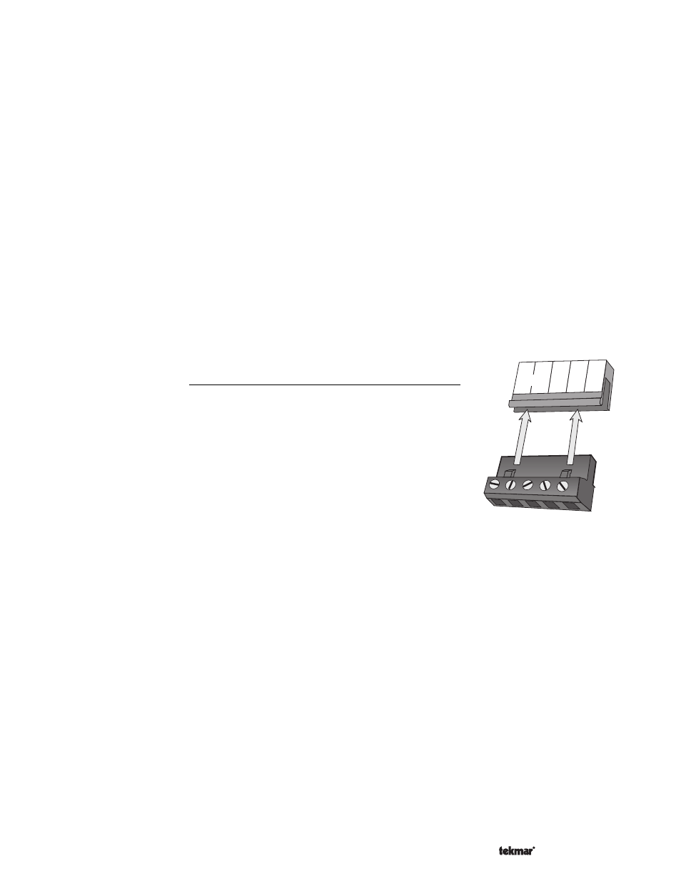
Connecting The Control
Make sure all power to the devices and terminal blocks is off and remove any
remaining jumpers from the terminals.
Reconnect the terminal blocks to the control by carefully aligning them with their respective
headers on the control and then pushing the terminal blocks into the headers. The terminal
blocks should snap firmly into place.
Install the supplied safety dividers between the unpowered sensor inputs and the powered
120 V (ac) or 24 V (ac) wiring chambers.
Apply power to the control. The operation of the control on power up is described in the
Sequence of Operation section of this brochure.