tekmar 362 Mixing Control Installation User Manual
Page 18
18 of 36
Copyright © D 362 -
12/08
Ω
Ω
V
17
18
Com
Mix
Boil
19
20
Out
Ω
V
V
3
4
N
L
Power
108 to 132 V (ac)
120 V (ac)
4
5
L Pmp
Mix
L
N
3
N
Power
Ω
V
V
1
2
Mix
Demand
20 to 260 V (ac)
14
15
Com
10K
UnO
Sw
16
Timer Switch
UnOccupied Switch
If an external timer (tekmar Timer 03
2) or switch is used, connect the two wires from
the external switch to the
Com and UnO Sw terminals (14 and 16). When these two
terminals are shorted together, the control registers an UnOccupied signal.
Note: The setback override in the schedule menu of the control overrides any external
signal that is present on the UnOccupied Switch terminals.
STEP FIVE
TESTING THE WIRING
Each terminal block
must be unplugged from its header on the control before power is applied for testing. To remove the terminal block,
pull straight down from the control.
The following tests are to be performed using standard testing practices and procedures and should only be carried out by properly
trained and experienced persons.
A good quality electrical test meter, capable of reading from at least 0 - 300 V (ac) and at least 0 - 2,000,000 Ohms, is essential to properly
test the wiring and sensors.
Test The Sensors
In order to test the sensors, the actual temperature at each sensor
location must be measured. A good quality digital thermometer with a
surface temperature probe is recommended for ease of use and accu-
racy. Where a digital thermometer is not available, a spare sensor can
be strapped alongside the one to be tested and the readings compared.
Test the sensors according to the instructions in the Data Brochure D
070.
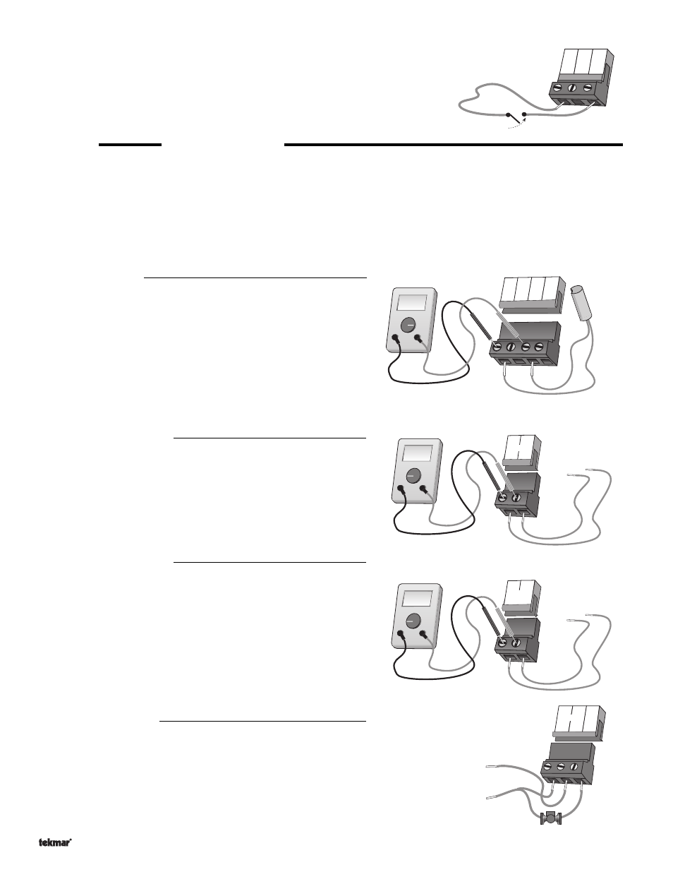
Test The Power Supply
Make sure exposed wires and bare terminals are not in contact with other
wires or grounded surfaces. Turn on the power and measure the voltage
between the
N and L terminals (3 and 4) using an AC voltmeter, the
reading should be between 108 and 132 V (ac).
Test The Powered Inputs
Mixing Demand
If a mixing demand is used, measure the voltage between the
Mix
Demand terminals (1 and 2). When the mixing demand device calls for
heat, you should measure between 20 and 260 V (ac) at the terminals.
When the mixing demand device is off, you should measure less than
5 V (ac).
Testing The Outputs
Mixing Pump (Mix Pmp)
If a mixing pump is connected to the terminal (5), make sure that power to the terminal
block is off and install a jumper between the
Power L and the Mix Pmp terminals (4 and
5). When power is applied to the
Power N and Power L terminals (3 and 4), the mixing
pump should start. If the pump does not turn on, check the wiring between the terminal
block and pump and refer to any installation or troubleshooting information supplied with
the pump. If the pump operates properly, disconnect the power and remove the jumper.