tekmar 362 Mixing Control Installation User Manual
Page 16
16 of 36
Copyright © D 362 -12/08
3
4
N
L
Power
120 V (ac)
1
2
Mix
Demand
24 to 240 V (ac)
3
4
Power Mix
Pmp
5
120 V (ac)
N
L
L
N
6
7
Boiler
T
T
T
T
8
9
Pwr
Mix
Opn
Cls/
Var
10
120 V (ac)
L
N
2
E
n
oit
c
e
S ,
e
c
n
e
u
q
e
S
• If a Slab Sensor 072 or 073 is used, install the Slab Sensor according to the installation instructions in the Data Brochure D 070
and run the wiring back to the control or RTU.
• If a Remote Display Module (RDM) 040 is used, install the RDM according to the installation instructions in the Data Brochure D 040
and run the wiring back to the control.
• If a Remote Start / Stop Module 039 is used, install the module according to the installation instructions in the Data Brochure D 039
and run the wiring back to the control.
• If a tekmar Zone Control is used, run the wires from the Zone Control to the 362. Refer to the instructions supplied with the Zone
Control.
• Run wire from other system components (pumps, boiler, actuator motors, etc.) to the control.
• Run wires from the 120 V (ac) power to the control. Use a clean power source to ensure proper operation. Multi-strand 16 AWG
wire is recommended for all 120 V (ac) wiring due to its superior flexibility and ease of installation into the terminals.
STEP FOUR
ELECTRICAL CONNECTIONS TO THE CONTROL
The installer should test to confirm that no voltage is present at any of the wires. Push the control into the base and slide it down until
it snaps firmly into place.
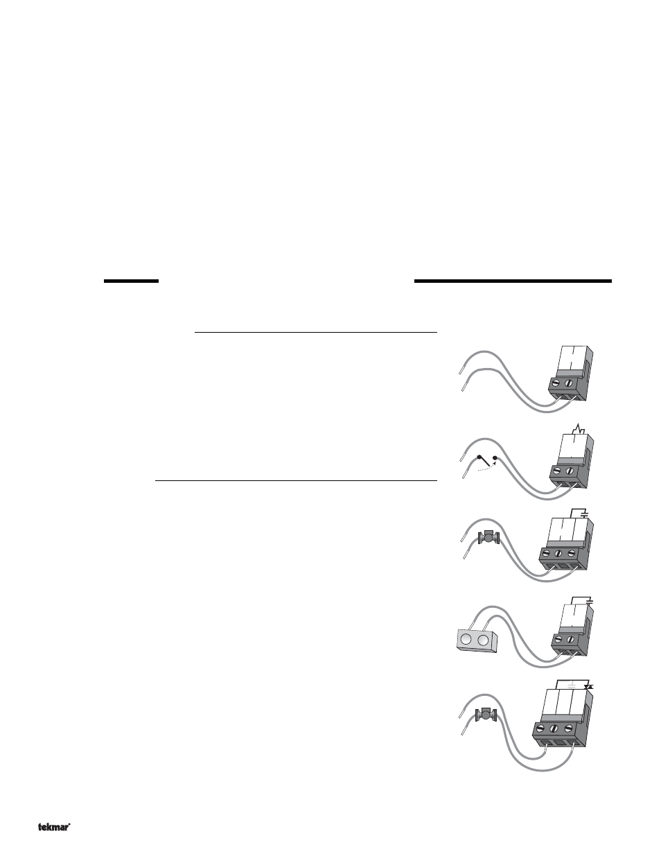
Powered Input Connections
120 V (ac) Power
Connect the 120 V (ac) power supply to the
Power N and Power L terminals (3 and 4).
This connection provides power to the microprocessor and display of the control. As
well, this connection provides power to the
Mix Pmp terminal (5) from the Power L
terminal (4).
Mixing Demand
To generate a Mixing Demand, a voltage between 24 V (ac) and 240 V (ac) must be
applied across the
Mix Demand terminals (1 and 2).
Output Connections
Mixing Pump Contact (Mix Pmp)
The
Mix Pmp output terminal (5) on the 362 is a powered output. When the relay in the
362 closes, 120 V (ac) is provided to the
Mix Pmp terminal (5) from the Power L terminal
(4). To operate the mixing pump, connect one side of the mixing pump circuit to terminal
5 and the second side of the pump circuit to the neutral (N) side of the 120 V (ac)
power supply.
Boiler Contact
The boiler terminals (6 and 7) are an isolated output in the 362. There is no power
available on these terminals from the control. These terminals are to be used as a
switch to either make or break the boiler circuit. When the 362 requires the boiler to fire,
it closes the contact between terminals 6 and 7.
Variable Speed Injection Pump
The 362 can vary the speed of a permanent capacitor, impedance protected or
equivalent pump motor that has a locked rotor current of less than 2.4 A. Most small
wet rotor circulators are suitable as described in Essay E 021. The 362 has an internal
overload protection fuse which is rated at 2.5 A 250 V (ac). Contact your tekmar sales
representative for details on the repair procedures if this fuse is blown.
Connect one of the wires from the variable speed injection pump to the
Cls / Var
terminal (10) on the 362. Connect the
Pwr Mix terminal (8) to the live (L) side of the 120
V (ac) power source. The other wire on the variable speed injection pump must be
connected to the neutral (N) side of the 120 V (ac) power supply.
• 120 V (ac) to be provided from a 15 A circuit breaker and must have a circuit disconnect installed.
• Connect ground wires to ground bus bar in wiring area.