Installation – tekmar 362 Mixing Control Installation User Manual
Page 15
15 of 36
Copyright © D 362 -
12/08
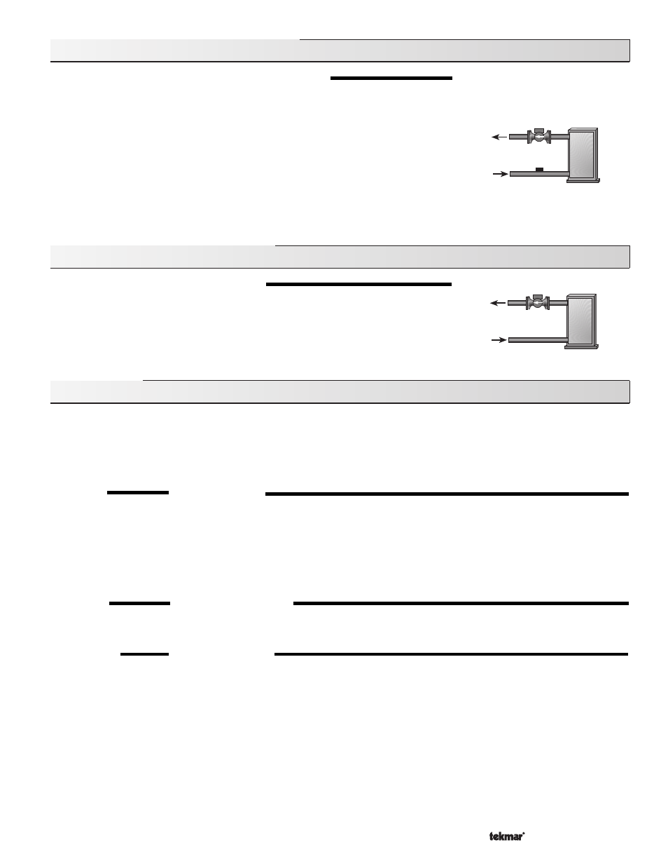
Section D2: Boiler Return Sensor
BOILER SENSOR ON THE RETURN (Boil SENS = RET)
The boiler sensor should be located on the boiler return if the 362 is one of many controls that
can call for boiler operation. When in the return mode, the 362 provides a boiler enable. The
362 no longer tries to control the boiler supply water temperature directly but allows the boiler
to operate at its operating aquastat setting. If this mode of operation is selected, the boiler
pump should either operate continuously or be operated in parallel with the Mixing Pump. The
boiler pump should not be operated by the boilers aquastat as this may lead to improper
cycling of the boiler because of inconsistent flow past the boiler return sensor.
When the mixing device begins to ramp up, the boiler contact on the 362 closes. The boiler
contact remains closed until the mixing device no longer requires heat. With the sensor on the
boiler return, the 362 is still capable of providing boiler return protection as described in
section A.
Section D3: No Boiler Sensor
NO BOILER SENSOR (Boil SENS = NONE)
The 362 is capable of operating without a boiler sensor if desired. Without a boiler sensor, the
362 is unable to provide boiler return protection. The boiler contact still functions without the
boiler sensor. When the mixing device begins to ramp up, the boiler contact on the 362 closes.
The boiler contact remains closed until the mixing device no longer requires heat. This type
of application is typical if the 362 is drawing heat from a heat source that already incorporates
some form of boiler return protection.
Installation
CAUTION
Improper installation and operation of this control could result in damage to the equipment and possibly even personal injury. It is your
responsibility to ensure that this control is safely installed according to all applicable codes and standards. This electronic control is
not intended for use as a primary limit control. Other controls that are intended and certified as safety limits must be placed into the
control circuit.
STEP ONE
GETTING READY
Check the contents of this package. If any of the contents listed are missing or damaged, please contact your wholesaler or tekmar sales
representative for assistance.
Type 362 includes:
One Mixing Control 362, One Outdoor Sensor 070, Two Universal Sensors 071, Data Brochures D 362,
D 070, D 001, User Brochure U 362, Application Brochures A 362, Essays E 003, E 021.
Note: Carefully read the details of the Sequence of Operation to ensure that you have chosen the proper control for your application.
STEP TWO
MOUNTING THE BASE
Remove the control from its base by pressing down on the release clip in the wiring chamber and sliding the control upwards. The base
is then mounted in accordance with the instructions in the Data Brochure D 001.
STEP THREE
ROUGH-IN WIRING
All electrical wiring terminates in the control base wiring chamber. The base has standard 7/8” (22mm) knockouts which accept common
wiring hardware and conduit fittings. Before removing the knockouts, check the wiring diagram and select those sections of the chamber
with common voltages. Do not allow the wiring to cross between sections as the wires will interfere with safety dividers which should
be installed at a later time.
Power must not be applied to any of the wires during the rough-in wiring stage.
• Install the Outdoor Sensor 070, Boiler Sensor 071, and Mixing Sensor 071 according to the instructions in the Data Brochure D070
and run the wiring back to the control.
• If a Room Temperature Unit (RTU) 062 or 063 is used, install the RTU according to the installation instructions in the Data Brochure
D 062 and run the wiring back to the control.