Rudder and elevator servo and linkage installation – E-flite Super Cub 25e ARF User Manual
Page 27
27
E-flite Super Cub 25e ARF Assembly Manual
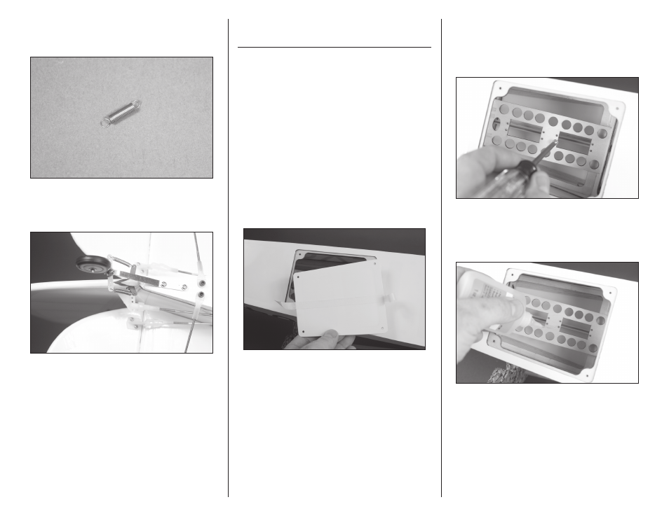
4. Use side cutters to remove the flat portion of the
springs. Use pliers to bend the outermost coil at
each end 90 degrees outward to form a hook.
5. Install the spring between the ruder tiller arm and
the steering tiller arm, attaching it to the center hole
in the steering arm.
6. Repeat steps 4 and 5 to install the remaining tail
wheel spring.
Rudder and Elevator
Servo and Linkage Installation
Required parts
Fuselage assembly Servo with hardware (2)
Rudder pushrod
Elevator pushrod
Nylon clevis (3)
Safety tubing (3)
Transmitter
Receiver
Receiver battery
Required Tools and Adhesives
Thin CA
Phillips screwdriver: #1
Pin vise
Drill bit: 5/64-inch (2mm)
Ruler
1. Remove the tape holding the servo hatch cover
on the fuselage. Set the cover aside. You may need
to use a covering iron to reseal the covering to the
fuselage if the tape lifts the covering.
2. Use a #1 Phillips screwdriver to thread a servo
mounting screw into each of the holes to cut threads
in the surrounding wood. Remove the screw before
moving to the next step. Use care not to press too
hard and damage the servo plate.
3. Apply 2–3 drops of thin CA in each of the holes
to harden the surrounding wood. This will harden
the threads so the screws do not easily strip the
surrounding wood.