Elevator installation – E-flite Super Cub 25e ARF User Manual
Page 20
20
E-flite Super Cub 25e ARF Assembly Manual
9. The upper rods are attached to the fin using
a 4-40 x 5/8-inch socket head cap screw and
4-40 locknut. Thread the nylon ends in or out as
necessary to set the length of the rods. Use a square
to check that the stabilizer remains square to the fin
on both the top and bottom of the fuselage.
Elevator Installation
Required parts
Fuselage assembly CA hinge (6)
Elevator (2)
Control horn (2)
2mm x 8mm self-tapping screw (4)
Required Tools and Adhesives
Thin CA
Phillips screwdriver: #1
Pin vise
Drill bit: 1/16-inch (1.5mm)
T-pins
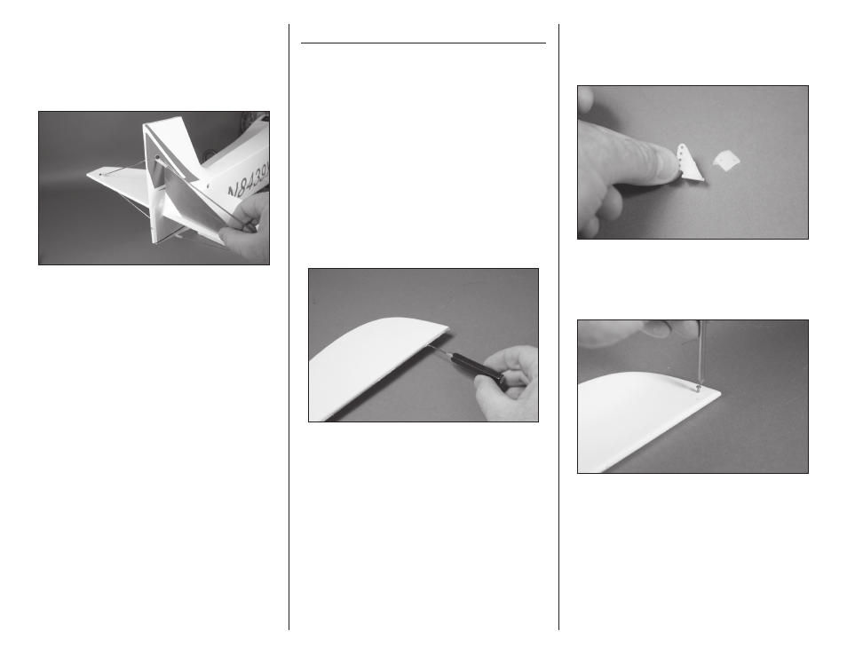
1. Use a pin vise and 1/16-inch (1.5mm) drill bit
to drill a hole in the center of each hinge slot in the
elevator and stabilizer to create a tunnel for the CA
to wick into. This will allow the CA to penetrate the
hinge, creating a better bond between the hinge and
surrounding wood.
2. Remove the control horn backplate from the
control horn using a hobby knife and #11 blade.
The backplate can be discarded as it is not used in
the assembly of your model.
3. Use a #1 Phillips screwdriver to thread a 2mm x
8mm self-tapping screw into each of the pre-drilled
holes to cut threads in the surrounding wood. Remove
the screw before moving to the next step.