Landing gear installation – E-flite Super Cub 25e ARF User Manual
Page 15
15
E-flite Super Cub 25e ARF Assembly Manual
Always balance your propeller. An unbalanced
propeller can cause vibrations to be transmitted
into the airframe, which could damage the
airframe or other components as well as
produce unwanted flight characteristics.
We recommend using the optional spinner
to enhance the looks of your model.
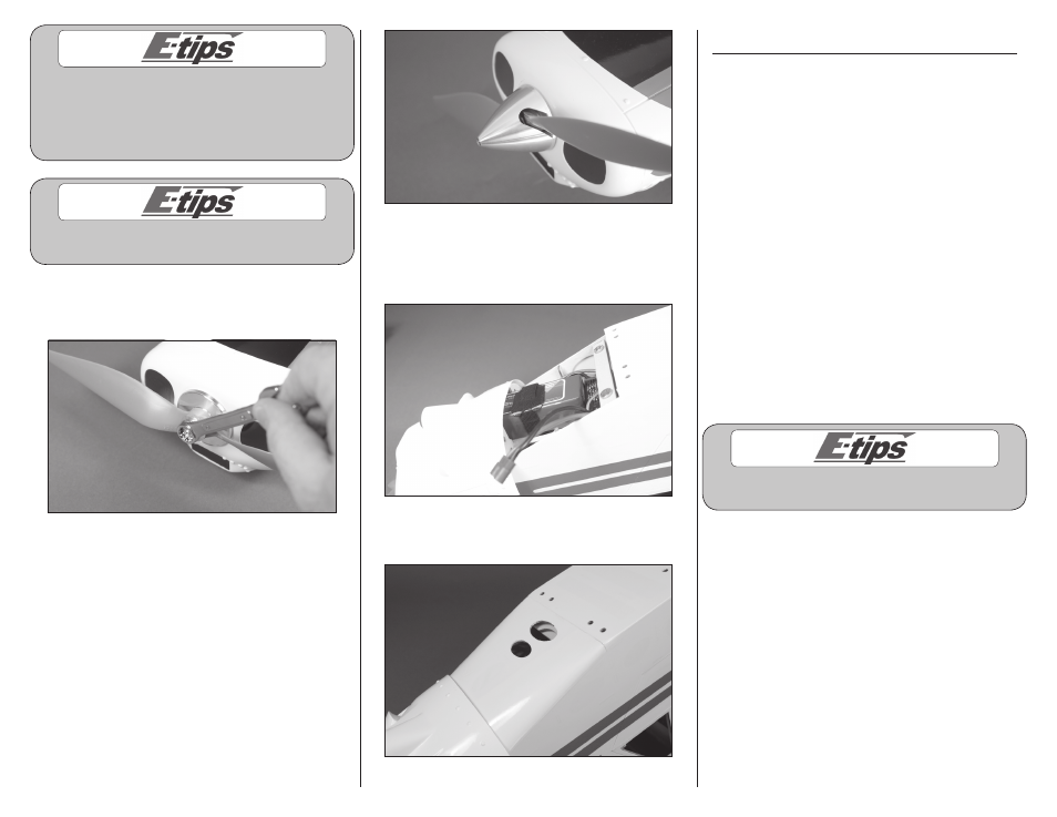
2. Slide the propeller/spinner on the motor shaft. Use
a 10mm box wrench to tighten the nut securing the
assembly to the motor shaft.
3. Place the spinner cone on the propeller. Use the
screw included with the spinner assembly and a
3/32-inch hex wrench to secure the cone in position.
Make sure the propeller is centered in the openings
so the spinner does not rub against the prop blades,
which could potentially cause them to fail.
4. Secure the motor battery in the fuselage using a
hook and loop strap. We recommend using hook and
loop tape between the battery and battery tray to
keep the battery from sliding on the tray during flight.
5. Place the battery hatch back into position
on the fuselage.
Landing Gear Installation
Required parts
Fuselage assembly Landing gear mount (4)
Wing strut tab (2) Landing gear leg (right and left)
4-40 lock nut (10) Axle (2)
Silicone tubing (4) Landing gear shock (2)
6-32-inch setscrew (2)
Main wheel, 3.35-inch (85mm) with hub (2)
2mm x 15mm self-tapping screw (8)
5/32-inch wheel collar with setscrew (2)
4-40 x 5/8-inch socket head cap screws (8)
4-40 x 1/2-inch socket head cap screw (2)
6-32 x 1/2-inch socket head cap screw (8)
Landing gear spreader
Required Tools and Adhesives
Hex wrench: 1.5mm, 3/32-inch, 5/64-inch,
1/8-inch
Flat blade screwdriver
Nut driver: 1/4-inch
Phillips screwdriver: #1
Threadlock
Always use threadlock on metal-to-metal fasteners
to prevent them from vibrating loose.