Rudder installation – E-flite Super Cub 25e ARF User Manual
Page 22
22
E-flite Super Cub 25e ARF Assembly Manual
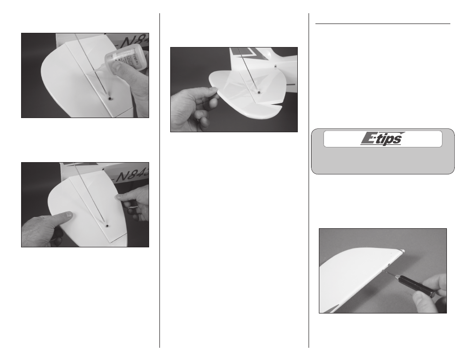
10. Saturate each hinge with thin CA. Apply CA to
both the top and bottom of the hinge.
11. Once the CA has cured, gently pull on the
control surface and stabilizer to make sure the hinges
are glued securely. If not, apply CA to those hinges
that are not glued and recheck.
12. Move the control surface through its range of
motion several times to break in the hinges. This
will reduce the initial load on the servo during your
first flights.
13. Repeat steps 1 through 12 to install the other
elevator half.
Rudder Installation
Required parts
Fuselage assembly CA hinge (3)
Control horn
Rudder tiller arm (2)
2mm nut
2mm x 12mm machine screw
2mm x 8mm self-tapping screw (2)
Required Tools and Adhesives
Thin CA
Phillips screwdriver: #1
Pin vise
Drill bit: 1/16-inch (1.5mm)
T-pins
Hobby knife with #11 blade
Optional Lighting Items
Clear LED light
Soldering iron
Heat shrink
36-inch lighting extension
The steps in the grey boxes are steps specific to the
lighting kit. If you will not be installing the lighting
kit you can skip the steps in the grey boxes.
1. Use a pin vise and 1/16-inch (1.5mm) drill bit
to drill a hole in the center of each hinge slot in the
rudder and fin to create a tunnel for the CA to wick
into. This will allow the CA to penetrate the hinge,
creating a better bond between the hinge and
surrounding wood.