E-flite Super Cub 25e ARF User Manual
Page 11
11
E-flite Super Cub 25e ARF Assembly Manual
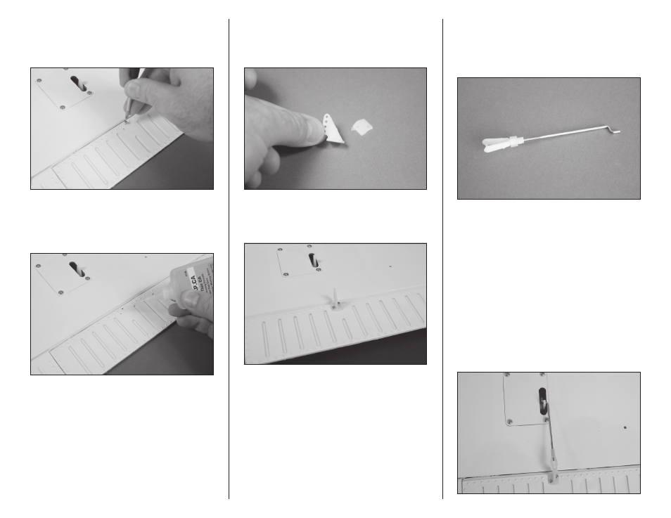
15. Use a #1 Phillips screwdriver to thread a
2mm x 8mm self-tapping screw into each of the pre-
drilled holes to cut threads in the surrounding wood.
Remove the screw before moving to the next step.
16. Apply 2–3 drops of thin CA in each of
the holes to harden the surrounding wood. This will
harden the threads so the screws do not easily strip
the surrounding wood.
17. Remove the control horn backplate from
the control horn using a hobby knife and #11
blade. The backplate can be discarded as it is not
used in the assembly of your model.
18. Install the servo horn using two 2mm
x 8mm self-tapping screws and a #1 Phillips
screwdriver.
19. Slide the small piece of silicone tubing
in a nylon clevis. Thread the clevis 12-turns on a
threaded pushrod wire. This will provide enough
threads in the clevis to be secure and allow for
adjustment of the linkage.
The aileron pushrod measures 2
9
/
16
-inches
(65mm), while the flap pushrod measures
2
5
/
16
-inches (59mm). Make sure to use the
correct linkage in the correct location.
20. Repeat steps 9 through 19 for the flap servo.
21. Attach the pushrod wire to the servo horn
using the bend in the wire. With the servo
centered, connect the clevis to the outer hole on
the control horn. Make sure the aileron is centered
when the clevis is connected. Adjust the clevis
as needed to center the aileron. Slide the tubing
over the forks of the clevis to keep it from opening
accidentally in flight.