E-flite Super Cub 25e ARF User Manual
Page 19
19
E-flite Super Cub 25e ARF Assembly Manual
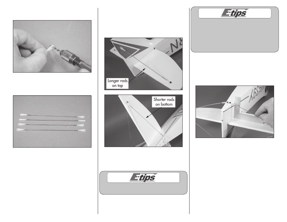
5. Use a pin vise and 7/64-inch (3mm) drill bit to
enlarge the hole in the eight nylon brace ends.
6. Thread the nylon ends on the two 2-56 x 6
1
/
2
-
inch threaded rods and the two 2-56 x 6
3
/
4
-inch
threaded rod.
7. Attach the nylon ends to the stabilizer using
two 4-40 x 5/8-inch socket head cap screws and
two 4-40 lock nuts. Use a 3/32-inch hex wrench
and 1/4-inch nut driver to tighten the hardware.
Leave the hardware slightly loose so the rods can
be positioned.
Important: The shorter 2-56 x 6
1
/
2
-inch threaded
rods are located on the bottom of the stabilizer,
and the shorter 2-56 x 6
3
/
4
-inch threaded rods
are located on the top of the stabilizer.
Always use threadlock on metal-to-metal fasteners
to prevent them from vibrating loose.
When installing the rods, make sure they are in
tension with one another slightly. This is what gives
the tail bracing its strength. Nothing should be
warped, and the anchor points are the two attach
points in the bottom of the fuselage. The fin should
not bend to one side and the stab should remain
flat. This may take some adjustment to get right.
8. Adjust the position of the nylon ends so the holes
align with the holes in the fuselage. Use a square
to make sure the stabilizer isn’t being overly-forced
into position. Use a 4-40 x 1/4-inch socket head
screw and a 3/32-inch hex wrench to install the
screws, securing the ends to the fuselage.