Motor and speed control installation – E-flite Super Cub 25e ARF User Manual
Page 13
13
E-flite Super Cub 25e ARF Assembly Manual
Motor and Speed Control Installation
Required parts
Fuselage
Motor with hardware
4-40 x 3/4-inch socket head cap screw (4)
Aluminum spacer, 3/8-inch (9.5mm) (4)
Speed control
Servo extension, 9-inch (228mm)
Required Tools and Adhesives
Threadlock
Phillips screwdriver: #1
Dental floss
Hex wrench: 3/32-inch
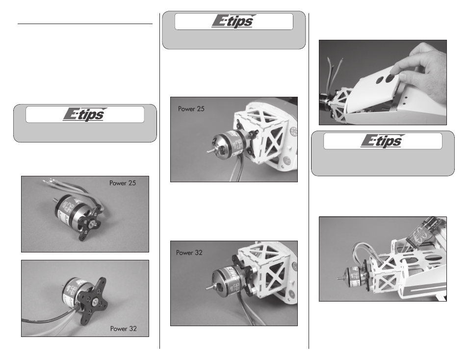
Always use threadlock on metal-to-metal fasteners
to prevent them from vibrating loose.
1. Attach the X-mount to the motor using the
hardware included with the motor and a #1
Phillips screwdriver.
Always use threadlock on metal-to-metal fasteners
to prevent them from vibrating loose.
2. (Power 25) Secure the motor to the firewall using
the four 4-40 x 3/4-inch socket head cap screws.
Use a 3/32-inch hex wrench to tighten the screws.
Make sure to use threadlock on these screws to
prevent them from vibrating loose.
2. (Power 32) Secure the motor to the firewall
using the four 3/8-inch (9.5mm) aluminum motor
standoffs and four 4-40 x 3/4-inch socket head cap
screws. Use a 3/32-inch hex wrench to tighten the
screws. Make sure to use threadlock on these screws
to prevent them from vibrating loose.
3. Remove the battery hatch by lifting it at the rear.
The rear is held in position with magnets, while the
front is held in position with dowels.
Matching the colors between the ESC and motor
when they are connected results in the correct
motor direction if using all E-flite components.
4. Connect the leads from the motor to the speed
control. Once connected, position the leads in the
fuselage to prevent them from interfering with the
operation of the motor or battery installation.