System overview, 2 controller-to-sensor cables – Banner A-GAGE MINI-ARRAY Series User Manual
Page 7
P/N 43298 rev. E
7
Banner Engineering Corp.
•
Minneapolis, MN U.S.A.
www.bannerengineering.com • Tel: 763.544.3164
MINI-ARRAY
®
Instruction Manual
System Overview
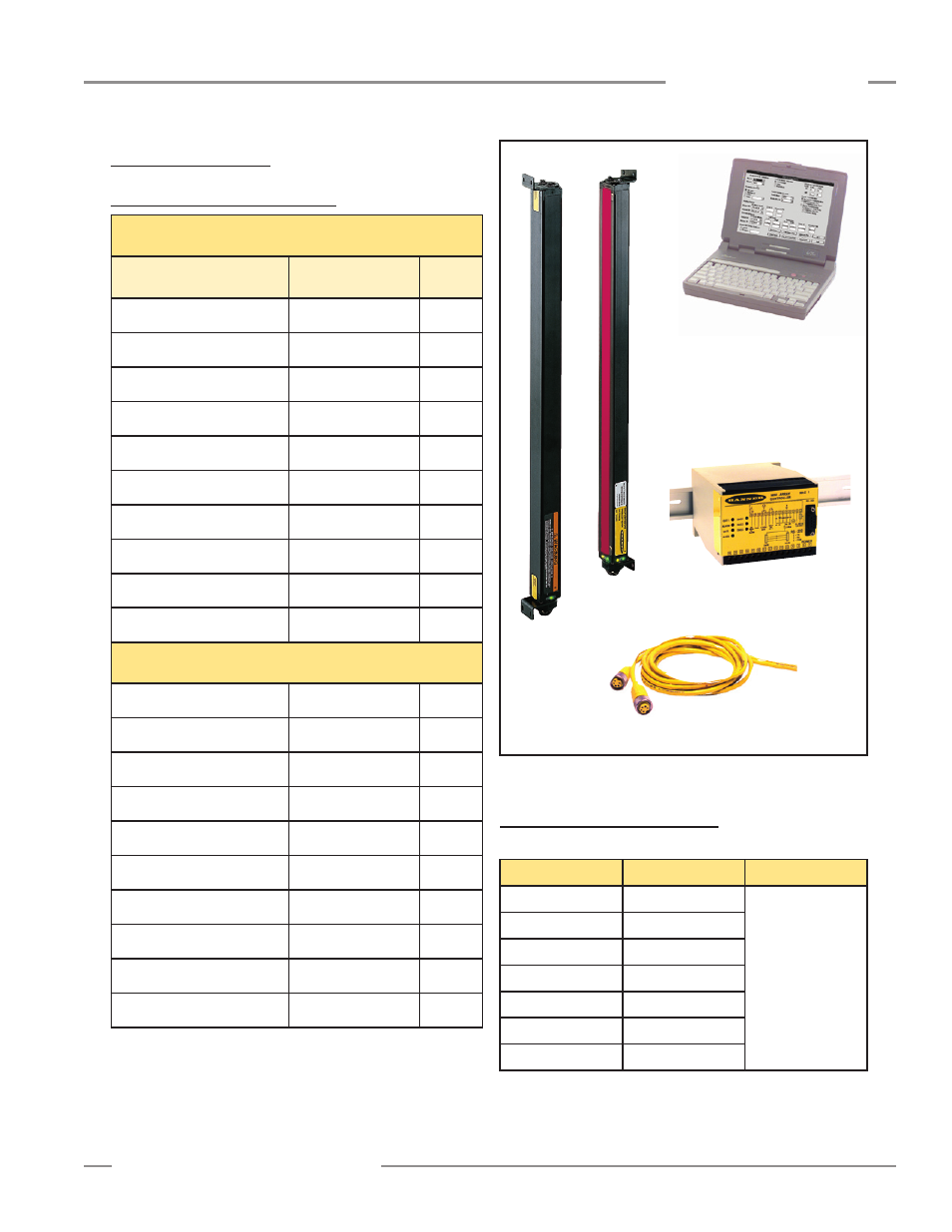
1.2 System Components
1.2.1 Emitter and Receiver Models
Figure 1-3. MINI-ARRAY system components
Quick-Disconnect
Cables
DIN-Rail-Mountable
Control Module
User-Supplied PC
Configure and monitor the System
with the supplied software and
a PC-compatible computer (see
Section 1.1.4).
Emitter Receiver
1.2.2 Controller-to-Sensor Cables
2 required per system
19.1 mm (3/4") beam spacing – 16 beams/foot
Emitter / Receiver
Models
Array Length
Total
Beams
BMEL616A / BMRL616A
133 mm (5.25")
8
BMEL1216A / BMRL1216A
286 mm (11.25")
16
BMEL1816A / BMRL1816A
438 mm (17.25")
24
BMEL2416A / BMRL2416A
591 mm (23.25")
32
BMEL3016A / BMRL3016A
743 mm (29.25")
40
BMEL3616A / BMRL3616A
895 mm (35.25")
48
BMEL4216A / BMRL4216A
1048 mm (41.25")
56
BMEL4816A / BMRL4816A
1200 mm (47.25")
64
BMEL6016A / BMRL6016A
1505 mm (59.25")
80
BMEL7216A / BMRL7216A
1810 mm (71.25")
96
9.5 mm (3/8") beam spacing – 32 beams/foot
BMEL632A / BMRL632A
143 mm (5.62")
16
BMEL1232A / BMRL1232A
295 mm (11.62")
32
BMEL1832A / BMRL1832A
448 mm (17.62")
48
BMEL2432A / BMRL2432A
600 mm (23.62")
64
BMEL3032A / BMRL3032A
752 mm (29.62")
80
BMEL3632A / BMRL3632A
905 mm (35.62")
96
BMEL4232A / BMRL4232A
1057 mm (41.62")
112
BMEL4832A / BMRL4832A
1210 mm (47.62")
128
BMEL6032A /BMRL6032A
1514 mm (59.62")
160
BMEL7232A / BMRL7232A
1819 mm (71.62")
192
Model
Length
QD Connector
QDC-515C
4.6 m (15')
5-pin Mini-style
straight
QDC-525C
7.6 m (25')
QDC-550C
15.2 m (50')
MAQDC-575C
22.7 m (75')
MAQDC-5100C
30.3 m (100')
MAQDC-5125C
37.9 m (125')
MAQDC-5150C
45.5 m (150')