Controller configuration, 4 blanking specifications – Banner A-GAGE MINI-ARRAY Series User Manual
Page 29
P/N 43298 rev. E
29
Banner Engineering Corp.
•
Minneapolis, MN U.S.A.
www.bannerengineering.com • Tel: 763.544.3164
MINI-ARRAY
®
Instruction Manual
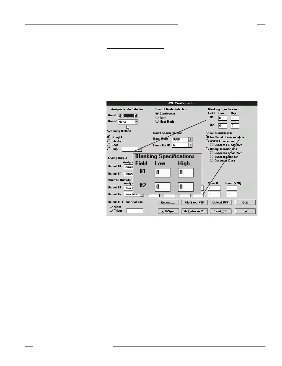
5.5.4 Blanking Specifications
A
Blanking
feature allows areas of the array to be blanked (made blind to activity
within an area).
Models MAC-1, MACP-1, MACN-1, MACV-1, and MACI-1
Blanking specifications allow either one or two areas of the array to be blanked (made
blind to activity within that area). Beams are numbered from the bottom (cable end)
of the sensors to the top of the sensors. The Low beam number and the High beam
number can be designated to define a Field to be blanked (see Figure 5-14). Zeros are
used as default settings to signify no blanking.
Figure 5-14. MINI-ARRAY software blanking specifications (models MAC-1, MACP-1,
MACN-1, MACV-1, and MACI-1)
Models MAC16P-1 and MAC16N-1
The controller can specify blanking of any light channel and save these specifications
in static memory. Blanking options are changed using the supplied software. Under
the MINI-ARRAY tasks, select the Alignment function to access the Alignment screen
(Figure 5-4).
The
Start
button causes the system to scan and update the Alignment screen.
Blanking commands include: Clear Blanking Fields, Restore Controller Settings, Auto
Blanking, Abort Auto Blanking, Save to File, Read From File, Cancel, OK, and Edit.
Clear Blanking Fields
removes all blanking specifications.
Restore Controller Settings
reads the previously saved blanking specifications from
the MINI-ARRAY controller.
Controller Configuration