Installation and alignment, 5 system power, 6 gate – Banner A-GAGE MINI-ARRAY Series User Manual
Page 18: 7 serial communication, 7 model mac16n-1 controller hookup, Rs-232, Mini-array
18
P/N 43298 rev. E
Banner Engineering Corp.
•
Minneapolis, MN U.S.A.
www.bannerengineering.com • Tel: 763.544.3164
MINI-ARRAY
®
Instruction Manual
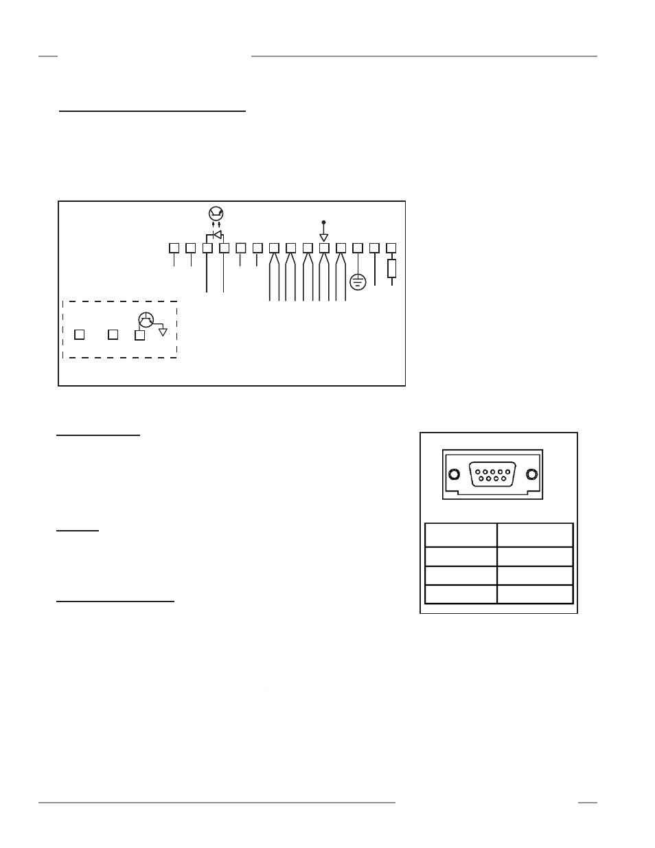
Figure 3-12. DB9 serial connector
3.5 System Power
Connect a 16 to 30V dc source to controller terminals #1 (V+) and #2 (V–). Connect
a good earth ground to terminal #3. A good earth ground is important for providing
electrical and RF noise immunity to the MINI-ARRAY System. The dc power source
must supply 1.25 amps (worst case) when using the longest (6') sensors. See
Specifications (Section 2) for more information.
3.6 Gate
Connect a switched 10 to 30V dc source as a gating input (if required) between
controller terminal #11 (+) and #12 (-). Voltage is typically switched by the open-
collector output transistor of a dc sensing device.
3.7 Serial Communication
RS-485 (Models MAC-1, MACP-1, and MACN-1 only)
Connect RS-485 lines (if used) to terminals #13 (+) and #14 (-).
RS-232
Prepare an RS-232 cable using a DB-9 male connector with the connections shown in
Figure 3-12.
NOTE:
DO NOT
use a “null modem” RS-232 cable.
RS-232
5
2
3
2- TX
3- RX
5- COM
DB-9 Pin #
Function
Ground (GND)
Receive (RX)
Transmit (TX)
5
3
2
Installation and Alignment
3.4.7 Model MAC16N-1 Controller Hookup
Terminals #15 through #30 are open-collector NPN transistor outputs rated at
30V dc max., 150 mA max.
They are protected against overload and short circuits.
All outputs are current sinking.
Controller terminal #15 (output #16) may be used as an output or as an alarm.
Whenever this output is active, the red Alarm LED is ON.
1
+
–
10-30V dc
Gate
16-30V dc
1.2 A Max.
2
3
4
5
6
7
8
9
10
13
14
F1
BROWN
BLUE
DRAIN (BARE)
BLACK
WHITE
EMITTER and
RECEIVER CABLES
V-
V+
Power
12
11
NC
NC
NC
NC
15
30
through
16 Solid-state Ouputs
150 mA Max each
Figure 3-11. Model MAC16N-1 hookup