Specifications, 4 controller dimensions, 3 controller specifications (continued) – Banner A-GAGE MINI-ARRAY Series User Manual
Page 12: Mini-array
12
P/N 43298 rev. E
Banner Engineering Corp.
•
Minneapolis, MN U.S.A.
www.bannerengineering.com • Tel: 763.544.3164
MINI-ARRAY
®
Instruction Manual
Status Indicators
(See Section 6.2 for
more information)
The following status LEDs are located on the front panel:
OUTPUT 1 (red) (name and function vary depending on model): Indicates active output
ALARM (red): Indicates that Output 2 or 16 is active (depending on model)
GATE (red): Indicates voltage is applied to GATE input
ALIGN (green): Indicates sensor aligned (excess gain >1x)
Plus three diagnostic LEDs:
DIAG1 (green): Indicates power is applied to the module
DIAG2 (red): Indicates receiver failure
DIAG3 (red): Indicates emitter failure
Sensor Scan Time
For all models: 55 microseconds per beam plus processing time.
The processing time is dependent on the scan analysis and the number of active outputs.
This timing assumes a straight scan, continuous, and TBB mode.
MAC-1, MACN-1 & MACP-1: 1 millisecond processing time.
MACV-1 & MACI-1: 1.5 milliseconds processing time.
MAC16N-1 & MAC16P-1: 2.3 to 7 milliseconds processing time.
Construction
Polycarbonate
Environmental Rating
NEMA 1 (IP20)
Operating Conditions
Temperature: -20° to +70°C (-4° to +158°F)
Maximum Relative Humidity: 95% (non-condensing)
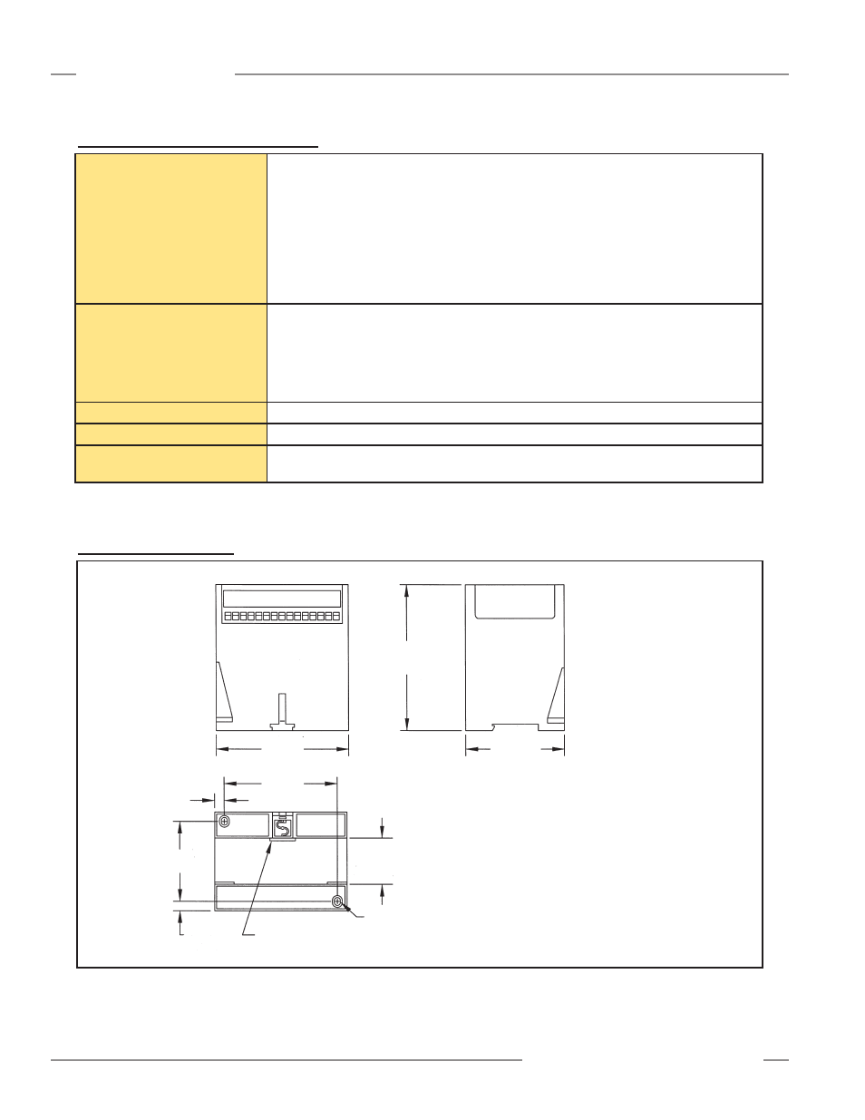
2.4 Controller Dimensions
Figure 2-2. Control module dimensions and mounting hole locations
75.0 mm
(2.95")
60.8 mm
(2.40")
7.1 mm
(0.28")
Din mounting tab
(supplied)
Slot for screws (2)
M3.5 x 0.6 mm (2)
35.0 mm
(1.38")
Din mounting slot
100.0 mm
3.94"
85.3 mm
3.36"
7.4 mm
(0.29")
110.0 mm
(4.33")
Combo Head (Phillips/Slotted Screws
M3.5 x 0.6 mm x 14 mm (2 ) (#6 x 0.5" equivalent) (supplied)
M3.5 Washers (2) (#6 equivalent) (supplied)
M3.5 mm x 0.6 mm Nuts (2) (#6 equivalent) (supplied)
Recommended torque is
16-20 in -lbs on mounting screws
Specifications
2.3 Controller Specifications (continued)