Installation and mechanical alignment, 1 emitter and receiver mounting, Mini-array – Banner A-GAGE MINI-ARRAY Series User Manual
Page 13
P/N 43298 rev. E
13
Banner Engineering Corp.
•
Minneapolis, MN U.S.A.
www.bannerengineering.com • Tel: 763.544.3164
MINI-ARRAY
®
Instruction Manual
Installation and Mechanical Alignment
3.1 Emitter and Receiver Mounting
Banner MINI-ARRAY emitters and receivers are small, lightweight, and easy to mount; the mounting brackets (supplied) allow ±30
degrees rotation.
From a common point of reference, make measurements to position the emitter and receiver in the same plane with their
midpoints directly opposite each other. Mount the emitter and receiver brackets using the M4 x 0.7 x 14 mm bolts and associated
mounting hardware (all supplied). See Figure 3-1.
Although the internal circuitry of the emitter and receiver can withstand heavy impulse forces, vibration isolators can be used
instead of the M4 bolts to dampen impulse forces and prevent possible damage from resonant vibration of the emitter or receiver
assembly. Two different Anti-Vibration Mounting Kits are available from Banner as accessories.
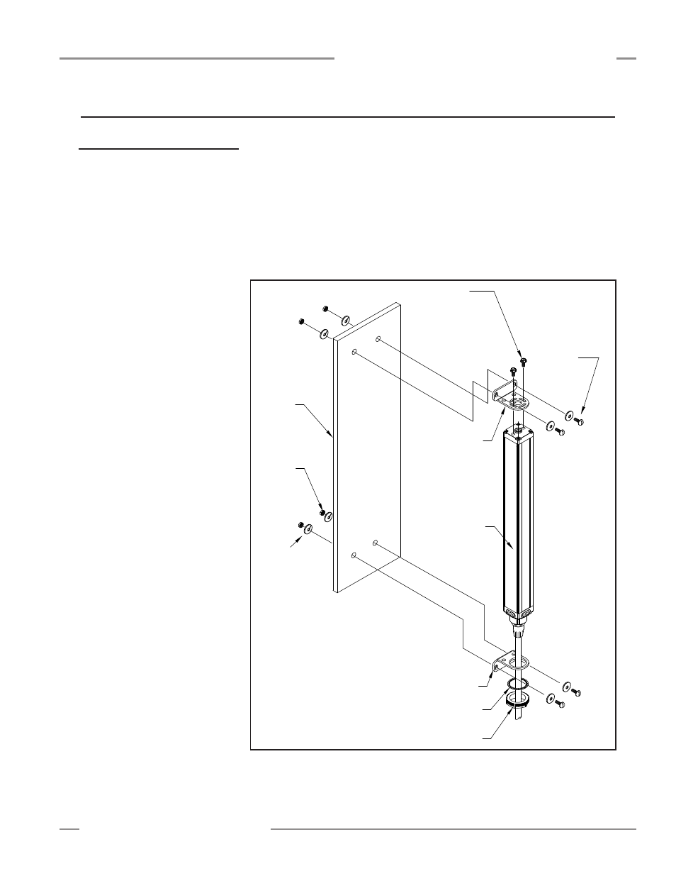
Figure 3-1. MINI-ARRAY emitter and receiver mounting hardware
Emitter
or
Receiver
Mounting
Mounting
Bracket
Surface
M4
Nut (4)
Washer (2)
with Compression
Slotted Hex Head
M4 x 10 mm
Bracket
Mounting
Nut
Washer
M4 x 14 mm
Screw with Flat
Washer
Compression
Washer (4)
Torque to
12 in. lbs.
(1.3 N-m)
3. Installation and Mechanical Alignment
P/N 48955 consists of 4 anti-vibration
mounts (M4 x 0.7 x 9.5 mm) and 8
M4 Keps nuts. These mounts are made
from BUNA-N rubber and are more
resistant to chemicals and oils.
P/N 12847 consists of 4 anti-vibration
mounts (M4 x 0.7 x 9.5 mm) and 8
M4 Keps nuts. These mounts are made
from natural rubber, which are less
chemically resistant than the 48955
mounts, but have a greater sheer force
spec at higher temperature.