System operation, 2 controller operating status indicators, Mini-array – Banner A-GAGE MINI-ARRAY Series User Manual
Page 36
36
P/N 43298 rev. E
Banner Engineering Corp.
•
Minneapolis, MN U.S.A.
www.bannerengineering.com • Tel: 763.544.3164
MINI-ARRAY
®
Instruction Manual
System Operation
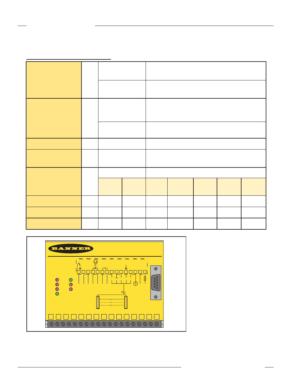
6.2 Controller Operating Status Indicators
MINI-ARRAY
CONTROLLER
2 - TX
3 - RX
5 - COM
RS-232
RS-232
MAC-1
OUT 1
ALARM
GATE
DIAG 1
DIAG 2
DIAG 3
ALIGN
POWER
15 14 13 12 11 10 9
8
7
6
5
4
3
2
1
15
30V
150mA
Max.
ALARM
500mA
Max
OUT 1
WH BK
BU
5 Wires
BR
-
+
RS485
-
+
10-30V DC
GATE
L2 L1
16-30V DC
1.2A Max.
14 13 12 11 10 9
8
7
6
5
4
3
2
1
T/R T/R DRN COM +12V
F1
EMTR
RCVR
Figure 6-2. Controller front panel
Output 1
(labeled OUT1, V out,
I out, OUT or OUT 1
depending on model)
Red
Models MAC-1,
MACP-1, MACN-1,
MACV-1, MACI-1:
displays the status of Output #1
Models MAC16N-1
MAC16P-1:
displays the status that at least one output is active
Alarm
Red
Models MAC-1,
MACP-1, MACN-1,
MACV-1, MACI-1:
displays the status of Output #2. Output #2 may be assigned
to an Analysis Mode or may be used as a system diagnostics
Alarm, or as a Trigger alarm for gating another MINI-ARRAY
System
Models MAC16N-1
MAC16P-1:
displays the status of Output #16
Gate
Red
All Models
displays the status of the Gate input
Align
Green
All Models
indicates proper sensor alignment and a clear light screen. This
indicator is ON when the green or green and yellow LEDs of the
receiver are ON
Diag 1,2,3
All Models
used in combination to indicate system status as shown below:
Normal
Condition
Receiver
Error
Emitter
Error
Emitter/
Receiver
Mismatch
Controller
Error
EEPROM
Error
ROM/RAM
Error
Diag 1
Green
ON
ON
ON
ON
OFF
OFF
OFF
Diag 2
Red
OFF
ON
OFF
ON
ON
OFF
ON
Diag 3
Red
OFF
OFF
ON
ON
OFF
ON
ON