Controller configuration, 1 communications setup, 2 alignment analysis – Banner A-GAGE MINI-ARRAY Series User Manual
Page 20
20
P/N 43298 rev. E
Banner Engineering Corp.
•
Minneapolis, MN U.S.A.
www.bannerengineering.com • Tel: 763.544.3164
MINI-ARRAY
®
Instruction Manual
Configuration of the MINI-ARRAY controller is accomplished with a Windows
®
menu-
style procedure, using the Banner-supplied software and a PC-compatible computer
running Windows
®
XP, Vista, or 7.
A serial data connection is made
between the computer and the DB9 connector on the controller (see Figure 3-12).
Parameter Setup Files (PSF) are programmed configurations that can be stored in the
control module’s non-volatile memory. The Banner software can store various PSFs in
computer files for instant call-up of a particular configuration.
The Banner software also provides two additional features: An Alignment screen and a
Diagnostics screen
5.1 Communications Setup
The MINI-ARRAY software permits serial communication via RS-232 between the MAC
controller and the PC. The minimum connections to the DB-9 connector on the
MINI-ARRAY Controllers are as follows:
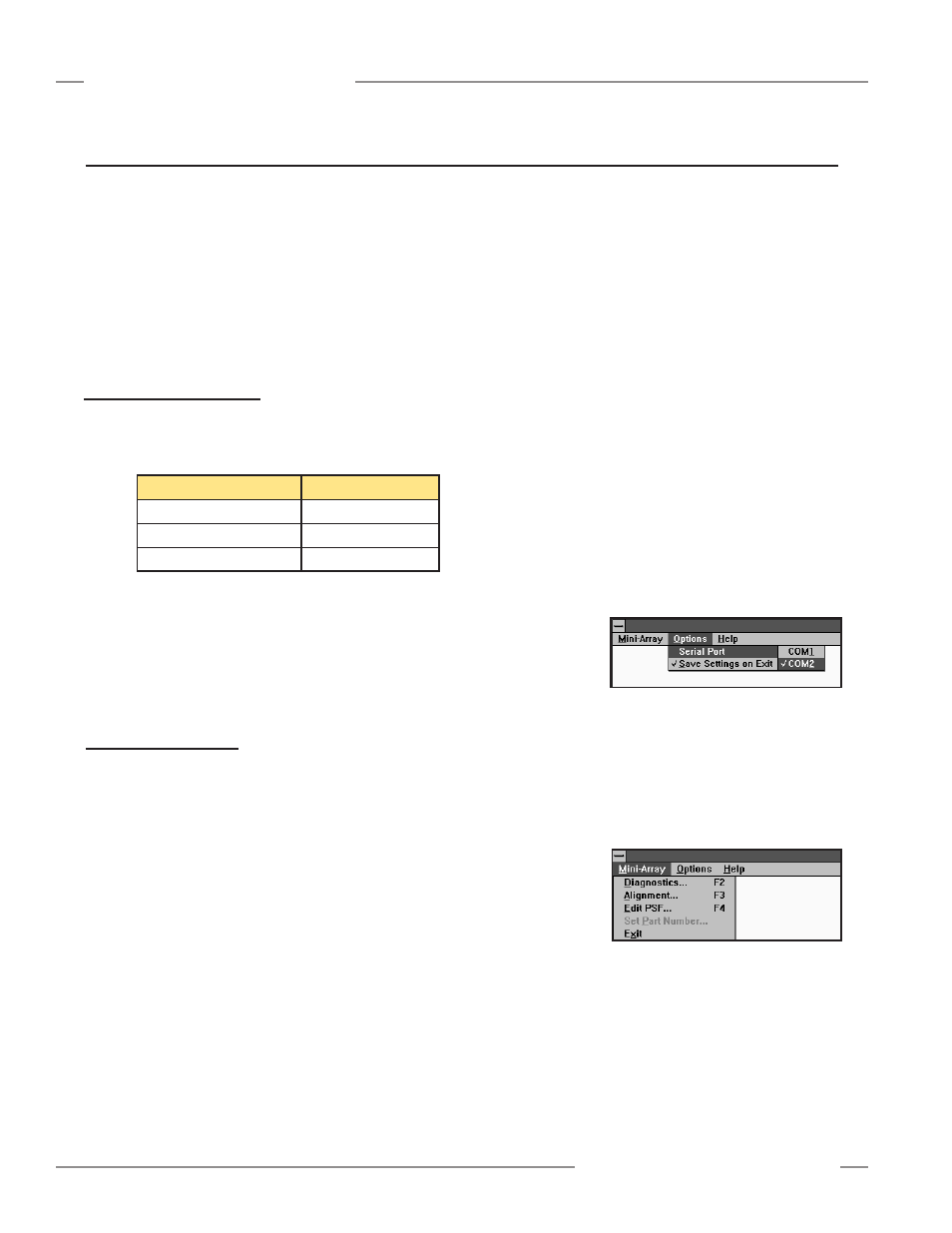
Figure 5-1. MINI-ARRAY software Option
menu
Figure 5-2. MINI-ARRAY software Main
menu
NOTE:
DO NOT
use a “null modem” RS-232 cable.
Configure the COM port of the PC by first selecting the
Options
menu (see Figure
5-1). The program supports serial communication via
the.COM1-COM20.port.
of the computer. Select
Options
, then select
Serial Port
(or
Enter
). Select either
COM1
or
COM2
. Check
Save
Settings on Exit
(if it is not already checked) to store
the COM port selection.
5.2 Alignment Analysis
Alignment status is continuously displayed by the green LED indicator on the Receiver
and the controller. When all unblanked beams are clear, and excess gain of all beams
is more than 3x, the green alignment indicators will be ON. When the excess gain
of one or more beams drops to between 3x and 1x, the green
ALIGN
LED on the
controller will remain ON, but the yellow LED on the receiver will come ON to indicate
a warning of marginal alignment. See Section 6 for more information about sensor
alignment.
One feature of the MINI-ARRAY software is a program that displays the status of
each beam in the array. This routine can be very helpful for final alignment or when
analyzing how the MINI-ARRAY is viewing objects in the sensing array. To launch this
program, select
Alignment...
under the
MINI-ARRAY
menu (see Figure 5-2), or
press the F3 key.
Controller Configuration
5. Controller Configuration
Pin Number of DB-9
Function
2
Transmit (TX)
3
Receive (RX)
5
Ground (GND)