Controller configuration – Banner A-GAGE MINI-ARRAY Series User Manual
Page 24
24
P/N 43298 rev. E
Banner Engineering Corp.
•
Minneapolis, MN U.S.A.
www.bannerengineering.com • Tel: 763.544.3164
MINI-ARRAY
®
Instruction Manual
After a PSF is configured, it may be sent to the controller. The PSF may also be saved
for call-up at a later time. Many PSFs may be saved within PC files for quick controller
configuration whenever a setup change is required.
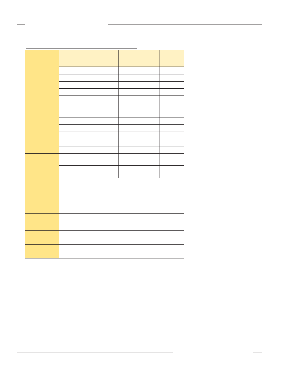
Parameter Setup Files Available for Each Controller Model
Analysis Mode
Selection
(See Section
5.5.3 for
descriptions of
these Analysis
Modes.)
MAC-1
MACP-1
MACN-1
MACV-1
MACI-1
MAC16N-1
MAC16P-1
ALL: All data passed to host
x
x
x
FBB: First Beam Blocked
x
x
x
LBB: Last Beam Blocked
x
x
x
TBB: Total Beams Blocked
x
x
x
CBB: Contiguous Beams Blocked
x
x
x
FBM: First Beam Made
x
x
x
LBM: Last Beam Made
x
x
x
TBM: Total Beams Made
x
x
x
CBM: Contiguous Beams Made
x
x
x
SEG: Segments
x
TRN: Transitions
x
VHS: Vehicle Separation
x
Blanking
Options
One or two fields may be
blanked
x
x
Blanking conditions are
unlimited
x
Output
Assignments
2 to 16 outputs, depending on model
Scanning
Methods
Straight Scan
Interlaced Scan
Edge Scan
Skip Scan
Control Mode
Selection
Continuous scanning
Gate Mode: scanning controlled by applying 10-30V dc to GATE input
Host Mode: scanning controlled by host computer or PLC
Serial
Communication
Defines baud rate and controller I.D.
Serial
Transmission
Activates serial data transmission and specifies data format.
Controller Configuration