Installation and alignment, 5 model maci-1 controller hookup, 6 model mac16p-1 controller hookup – Banner A-GAGE MINI-ARRAY Series User Manual
Page 17: Mini-array, Current outputs 1 and 2, Alarm, Instruction manual
P/N 43298 rev. E
17
Banner Engineering Corp.
•
Minneapolis, MN U.S.A.
www.bannerengineering.com • Tel: 763.544.3164
MINI-ARRAY
®
Instruction Manual
Installation and Alignment
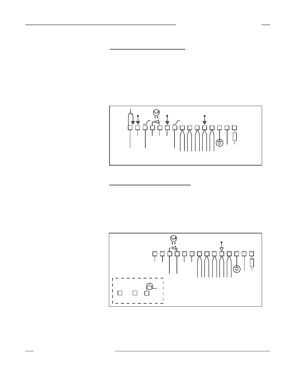
3.4.5 Model MACI-1 Controller Hookup
Current outputs 1 and 2:
Controller terminal #9 (I out 1) and #13 (I out 2) are analog
current outputs. The load for analog current Output #1 should be connected between
an external 16 to 30V dc power supply and terminal #9. The load for analog current
Output #2 should be connected between an external 16 to 30V dc power supply
and terminal 13. The load external power supply return should be common with the
controller power supply return. Both outputs are current sinking.
Alarm:
Controller terminal #15 ( ALARM) is an open-collector NPN transistor rated at
30V dc max., 150 mA max. It is protected against overload and short circuits.
1
+
–
10-30V dc
Gate
16-30V dc
1.2 A Max.
2
3
4
5
6
7
8
9
10
13
14
15
F1
BROWN
BLUE
DRAIN (BARE)
BLACK
WHITE
EMITTER and
RECEIVER CABLES
V-
V+
30V
150 mA
Max.
ALARM
Power
12
11
Com
Com
4-20 mA
I out 2
4-20 mA
I out 1
3.4.6 Model MAC16P-1 Controller Hookup
Terminals #15 through #30 are open-collector PNP transistor outputs rated at 30V
dc max., 150 mA max. They are protected against overload and short circuits. The
isolated gate input is at pins 11 and 12.
Controller terminal #15 (output #16) may be used as an output or as an alarm.
Whenever this output is active, the red Alarm LED is ON.
All outputs are current sourcing.
Figure 3-9. Model MACI-1 hookup
1
+
–
10-30V dc
Gate
16-30V dc
1.2 A Max.
2
3
4
5
6
7
8
9
10
13
14
15
30
F1
BROWN
BLUE
DRAIN (BARE)
BLACK
WHITE
EMITTER and
RECEIVER CABLES
V-
V+
Power
12
11
NC
NC
NC
NC
through
16 Solid-state Ouputs
V+
150 mA Max each
Figure 3-10. Model MAC16P-1 hookup