Installation and mechanical alignment, 2 controller mounting, 3 emitter and receiver hookups – Banner A-GAGE MINI-ARRAY Series User Manual
Page 14
14
P/N 43298 rev. E
Banner Engineering Corp.
•
Minneapolis, MN U.S.A.
www.bannerengineering.com • Tel: 763.544.3164
MINI-ARRAY
®
Instruction Manual
Installation and Mechanical Alignment
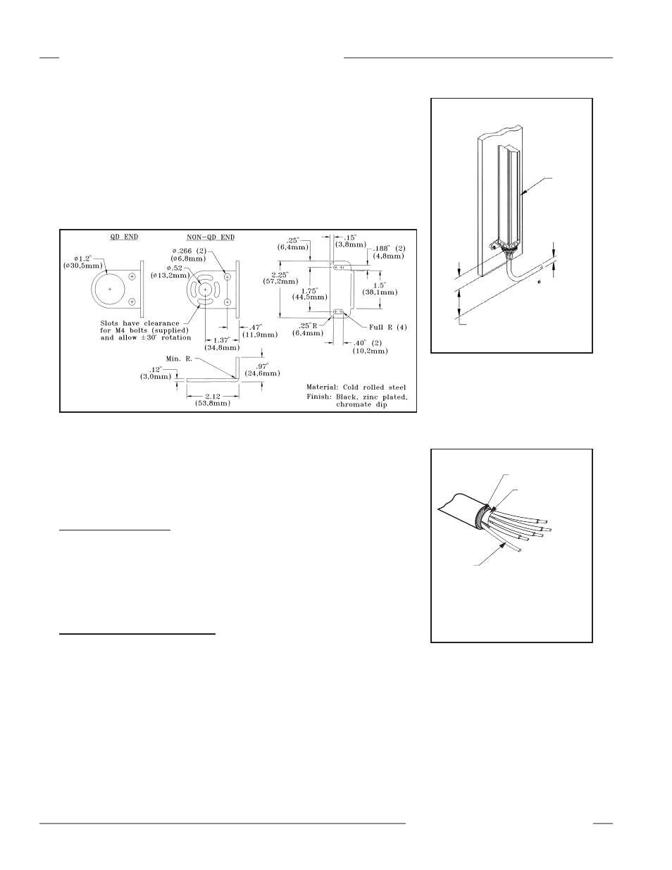
Figure 3-2. MINI-ARRAY emitter and receiver mounting bracket dimensions
Mount the emitter and receiver in their mounting brackets (shown in Figure 3-1),
and position the red lenses of the two units directly facing each other. The connector
ends of both sensors must point in the same direction. Measure from one or more
reference planes (i.e., the floor) to the same points on the emitter and receiver to
verify their mechanical alignment. If the sensors are positioned exactly vertical or
exactly horizontal, a carpenter’s level may be useful for checking alignment. Extending
a straight-edge or a string between the sensors may help with positioning. Also check
by eye for line-of-sight alignment. Make any necessary final mechanical adjustments,
and hand-tighten the bracket hardware. See Section 5 for information on alignment
indicators and the use of the alignment software supplied with the controller.
Connect the shielded cables to the emitter and receiver, and route them to the
controller location. Follow the local wiring code for low-voltage dc control cables. The
same cable type is used for both emitter and receiver (two cables required per system).
Cut the cables to length after making sure they are routed properly. Remove cable braid
at the controller connection points (see Figure 3-4).
3.2 Controller Mounting
The controller must be installed inside an enclosure with a NEMA (or IEC) rating
suitable for the operating environment.
Mounting dimensions for the controller are shown in Figure 2-2. The controller is
supplied with M3.5 x 0.6 hardware for direct mounting to a surface, or it can be
mounted onto standard 35 mm DIN rail.
3.3 Emitter and Receiver Hookups
Emitter and receiver cables connect in parallel to controller terminals #4 through #8.
Connect the wires from both sensor cables, as follows:
Terminal 4
Brown
Terminal 5
Blue
Terminal 6
Bare
Terminal 7
Black
Terminal 8
White
Trim off the foil shield and the braided shield at the point where the wires exit the cable
(see Figure 3-4).
The “drain wire” is the uninsulated stranded
wire which runs between the braided shield
and the foil shield. Remove the foil shield
and braided shield at the point where the
wires exit the cable.
Figure 3-4. Emitter/receiver cable
preparation
Trim braided shield flush
with cable
Trim foil shield flush
with cable
Uninsulated
drain wire
Emitter or
Receiver
8.1 mm
(0.32") max.
0.5" (13 mm) radius minimum bend
71 mm
2.8"
Figure 3-3. Quick-disconnect cable
clearances