System overview, 1 system features, Mini-array – Banner A-GAGE MINI-ARRAY Series User Manual
Page 4: Instruction manual, Figure 1-2. a-gage mini-array system features, Banner engineering corp, Minneapolis, mn u.s.a
4
P/N 43298 rev. E
Banner Engineering Corp.
•
Minneapolis, MN U.S.A.
www.bannerengineering.com • Tel: 763.544.3164
MINI-ARRAY
®
Instruction Manual
System Overview
1.1 System Features
Built-in features simplify the operation of the A-GAGE MINI-ARRAY system.
Programmable beam blanking accommodates machine components or other fixtures
that must remain in or move through the light screen. Blanking is set by using the
included configuration software. See Section 5.5.4 for more information.
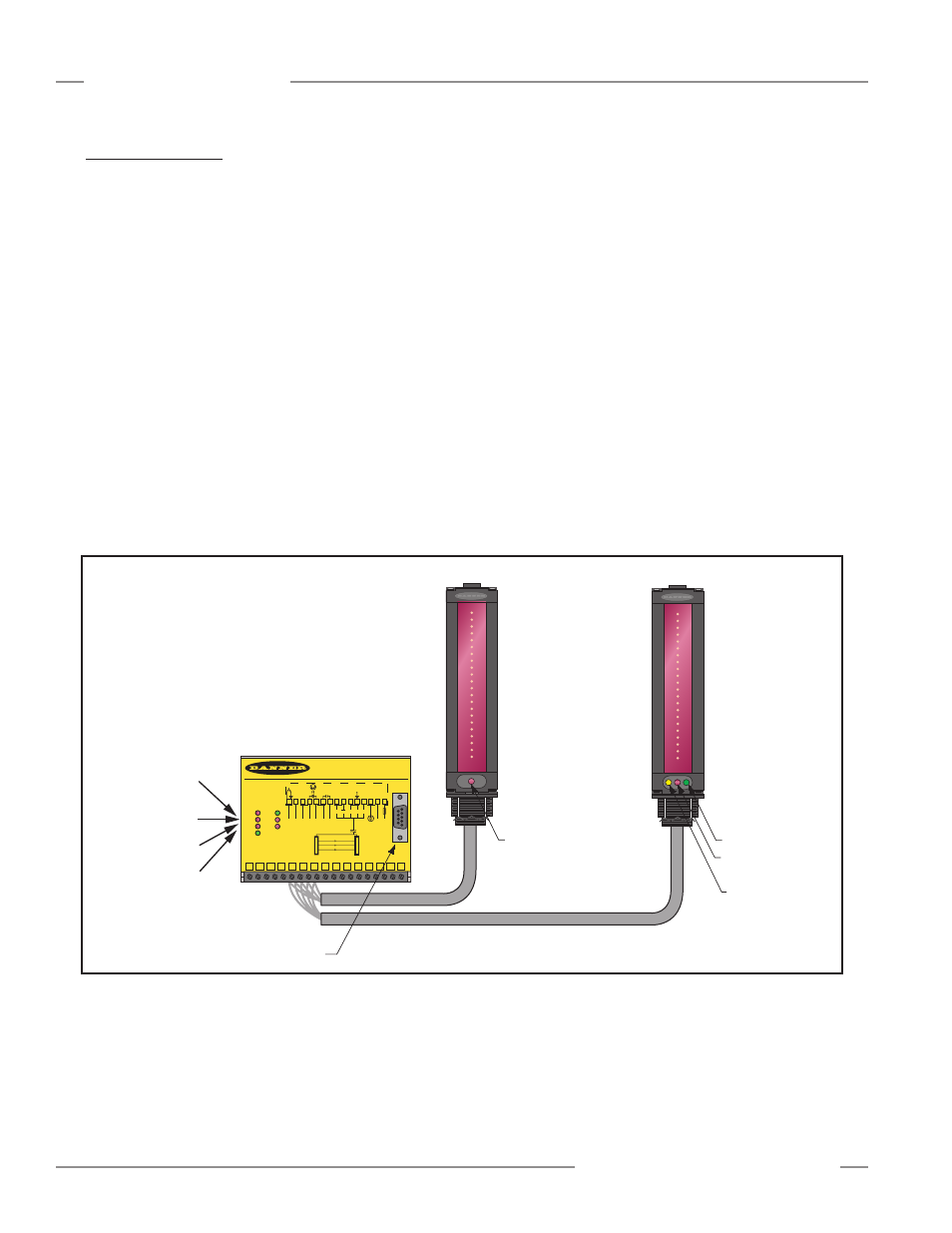
Built-in diagnostic programming and easy-to-see indicators on the sensors and the
control module make alignment and troubleshooting easy (Figure 1-2). The emitter
has a red LED that signals proper operation. The receiver has three bright LEDs:green
signals that the sensors are properly aligned; yellow signals marginal alignment; and
red signals misalignment or a blocked condition. The control module has seven status
indicators: 5 red LEDs signal when outputs are conducting (see Section 3 for more
information), Alarm output conducting, and gate signal received; a green LED signals
that the sensors are properly aligned. DIAG 1, 2, and 3 LEDs indicate system status. A
key to the diagnostics codes is printed on the side of the control module for simplified
troubleshooting (see Section 6.3).
The MINI-ARRAY System provides a wide selection of sensing and output options,
including: measurement (“scan analysis”) modes and scanning methods that can
determine the target object’s location, overall size, total height or total width. Scanning
may be continuous or controlled by a host process controller or a gate sensor. Some
models (MAC1, MACP, MACN) support RS-485, where up to 15 systems may be
networked.
Figure 1-2. A-GAGE MINI-ARRAY System features
Emitter
DIN-Rail-Mountable Control Module
Receiver
MINI-ARRAY
CONTROLLER
2 - TX
3 - RX
5 - COM
RS-232
RS-232
MAC-1
OUT 1
ALARM
GATE
DIAG 1
DIAG 2
DIAG 3
ALIGN
POWER
Red Discrete
Output #1 LED
Red
Operational
LED
Green Alignment LED
Red Blocked LED
Yellow Marginal
Alignment LED
Red Alarm
(Discrete Output #2) LED
Red Gate LED
Green Align LED
RS-232 Port
15 14 13 12 11 10 9
8
7
6
5
4
3
2
1
15
30V
150mA
Max.
ALARM
500mA
Max
OUT 1
WH BK
BU
5 Wires
BR
-
+
RS485
-
+
10-30V DC
GATE
L2 L1
16-30V DC
1.2A Max.
14 13 12 11 10 9
8
7
6
5
4
3
2
1
T/R T/R DRN COM +12V
F1
EMTR
RCVR