Installation and mechanical alignment, 4 controller wiring and output hookups, 1 model mac-1 controller hookup – Banner A-GAGE MINI-ARRAY Series User Manual
Page 15: 2 model macp-1 controller hookup, Mini-array, Output 1, Alarm, Instruction manual
P/N 43298 rev. E
15
Banner Engineering Corp.
•
Minneapolis, MN U.S.A.
www.bannerengineering.com • Tel: 763.544.3164
MINI-ARRAY
®
Instruction Manual
Installation and Mechanical Alignment
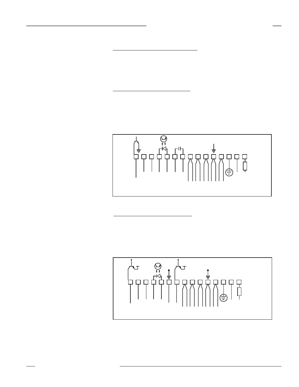
Figure 3-5. Model MAC-1 hookup
1
+
–
+
–
10-30V dc
Gate
16-30V dc
1.2 A Max.
2
3
4
5
6
7
8
9
10
11
12
13
14
15
F1
BROWN
BLUE
DRAIN (BARE)
BLACK
WHITE
EMITTER and
RECEIVER CABLES
V–
V+
RS485
500 mA
Max.
Out 1
30V
150 mA
Max.
ALARM
Power
3.4 Controller Wiring and Output Hookups
Cable clearance dimensions for the arrays are shown in Figure 3-3.
Controller connections are made via the wiring terminals along the front surface
of each module. Emitter and receiver hookups and controller outputs are shown in
Figures 3-5 through 3-11.
3.4.1 Model MAC-1 Controller Hookup
Output 1:
Controller terminals #9 and #10 (OUT1) are reed relay contacts rated
at 125V ac/dc max., 10 VA max. resistive (i.e., non-inductive) load. It may be
programmed as either normally open or normally closed.
Alarm:
Controller terminal #15 (Alarm) is an open-collector NPN transistor switch
rated at 30V dc max., 150 mA max. It is protected against overload and short circuits.
3.4.2 Model MACP-1 Controller Hookup
Output 1:
Controller terminal #9 (OUT1) is an open-collector PNP transistor switch
rated at 30V dc max., 150 mA max. It is protected against overload and short circuits.
Alarm:
Controller terminal #15 (ALARM) is an open-collector PNP transistor switch
rated at 30V dc max., 150 mA max. It is protected against overload and short circuits.
Both outputs are current sourcing.
Figure 3-6. Model MACP-1 hookup
1
+
–
+
–
10-30V dc
Gate
16-30V dc
1.2 A Max.
2
3
4
5
6
7
8
9
10
11
12
13
14
15
F1
BROWN
BLUE
DRAIN (BARE)
BLACK
WHITE
EMITTER and
RECEIVER CABLES
V-
V+
RS485
Com
30V
150 mA
Max.
ALARM
30V
150 mA
Max.
Out
Power
V+
V+