Controller configuration, 6 control mode selection, 6 serial communication – Banner A-GAGE MINI-ARRAY Series User Manual
Page 32: 1 serial transmission, Host control
32
P/N 43298 rev. E
Banner Engineering Corp.
•
Minneapolis, MN U.S.A.
www.bannerengineering.com • Tel: 763.544.3164
MINI-ARRAY
®
Instruction Manual
Figure 5-20. Serial communication
options
Figure 5-19. MINI-ARRAY software: Serial
Communication Parameter
selection
5.5.6 Control Mode Selection
The controller can be programmed for Continuous scanning, Gated scanning, or for
Host mode. The module offers an optically-isolated
Gate
input, which is energized
by application of 10 to 30V dc. Gating is typically accomplished using a dc presence
sensing device.
Host mode
allows the array to be gated by a host computer or
programmable logic controller (PLC).
Host Control
All MINI-ARRAY Systems can communicate with a host computer or controller via RS-
232 serial protocol. In addition, controller models MAC-1, MACN-1, and MACP-1 also
can communicate via RS-485. The host can direct the MINI-ARRAY System to scan on
demand and/or receive the scan data directly from the MINI-ARRAY System in binary
or ASCII form. Selectable communication baud rates are 9600, 19200, and 38400.
5.6 Serial Communication
The MINI-ARRAY System can communicate with its host computer or controller via
either RS-232 (all models) or RS-485 (MAC-1, MACN-1, MACP-1) serial protocol.
The host can direct the MINI-ARRAY to scan on demand, and/or receive the scan
data directly from the MINI-ARRAY System in Binary or ASCII form, Selectable
communication baud rates are 9600, 12000, and 38400 (Figure 5-19). Protocol is
one start bit, one stop bit, 8 data bits, and even parity. See the Appendix for more
information on data formats.
When RS-485 communication is used, each controller module may be assigned
a controller ID. Select letter A through O for individual identification of up to 15
Controllers on a RS-485 “party line.”
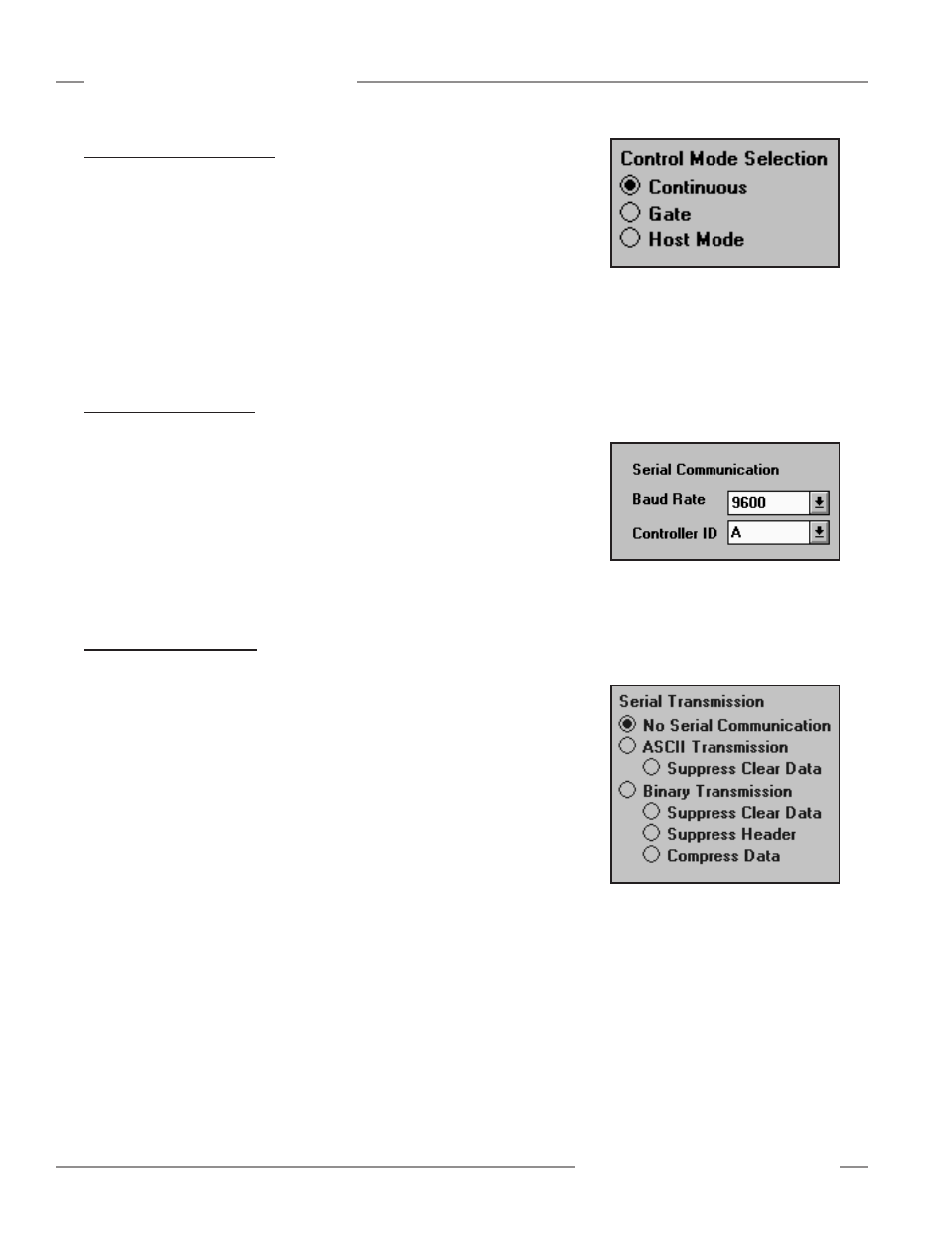
5.6.1 Serial Transmission
Serial Transmission activates the serial port, specifies the data format, and provides
data suppression options. If No Serial Communication is selected (default), the serial
port does not transmit sensing data. See Figure 5-20.
ASCII Transmission specifies that the scan data will use the ASCII format. ASCII
Transmission has one suppression option called Suppress Clear Data, which means
that data is sent one time when the array is completely clear (i.e., when no beams are
blocked) and no further data is sent until one or more beams are blocked.
Binary Transmission specifies that the scan data will use the binary format. The binary
format has three suppression options. The first option is Suppress Clear Data, which
means that data is sent once when the array is completely clear (i.e., when no beams
are blocked), and no further data is sent until one or more beams are blocked. The
Suppress Header option reduces the size of the controller serial message by three
bytes. Header bytes consist of the two byte start string plus the termination byte. The
Compress Data option, in many cases, reduces the number of data bytes sent for each
analysis mode from two to one byte.
See the Appendix for additional information.
Figure 5-18. MINI-ARRAY software:
control mode selection
Controller Configuration