Controller configuration – Banner A-GAGE MINI-ARRAY Series User Manual
Page 26
26
P/N 43298 rev. E
Banner Engineering Corp.
•
Minneapolis, MN U.S.A.
www.bannerengineering.com • Tel: 763.544.3164
MINI-ARRAY
®
Instruction Manual
Hysteresis (Low and High) determines how much change must occur at each set
point to cause the associated output to change state. Hysteresis avoids unstable
output conditions (e.g., chattering of the output) when the scanning condition exactly
matches one of the set points. The default setting for hysteresis is one beam less than
the Low Set Point and one beam more than the High Set Point.
Scan # is the number of consecutive scans of the array required before the associated
output is updated. The controller can be programmed for from one to nine consecutive
scans. The scan data MUST BE THE SAME for all consecutive scans for the outputs to
be updated.
Invert (Y/N) allows the output to be normally open (No) or normally closed (Yes).
Models MAC16P-1, MAC16N-1 — Discrete Outputs
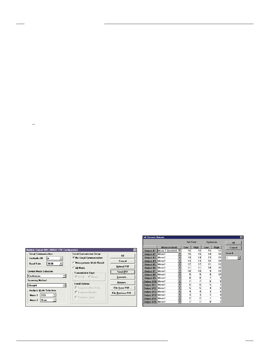
The sixteen discrete outputs are programmed using the Outputs button on the Multiple
Output MINI-ARRAY PSF Configuration screen (Figure 5-10).
The Outputs Button launches the Edit Discrete Outputs screen (Figure 5-11, which
allows the Set Points and Hysteresis levels to be defined for each output. Set Point
and Hysteresis values may be configured individually for each output and assigned
to either Meas1 or Meas2. Set Point level defines the condition where the output is
in the “true condition”. For a typical application, the output will be active when the
Measurement mode result is between the set point limits. If the inverted option is
specified, the output will be inactive when the Measurement mode result is between
the set point limits (i.e., the true condition). The Hysteresis Low and High levels
determine when the output will change back to the false condition.
The SEG measurement mode uses the Set Point Low and High levels to define
segmentation of the light screen. As an example, Output #1 Set Point Low is 5 and
the Set Point High is 20. These two values define beams 5 through 20 as a segment.
Whenever any of these beams are blocked, this segment of the light screen is
considered blocked, and Output #1 will be active (or inactive, if “Inverted” is selected).
For the SEG measurement mode, the Hysteresis specification is inactive. The Scan
Number may be used to change the number of consecutive scans necessary to change
the output. When the Scan Number is set to one, the output will change after only
one scan. If the Scan Number is set to five, the outputs will not change unless the
condition is true for five consecutive scans.
Figure 5-10. PSF Configuration screen (models MAC16P-1 and
MAC16N-1)
Figure 5-11. Edit Discrete Outputs screen
Controller Configuration