Controller configuration, 2 output programming – Banner A-GAGE MINI-ARRAY Series User Manual
Page 25
P/N 43298 rev. E
25
Banner Engineering Corp.
•
Minneapolis, MN U.S.A.
www.bannerengineering.com • Tel: 763.544.3164
MINI-ARRAY
®
Instruction Manual
5.5 Creating New Parameter Setup Files (PSFs)
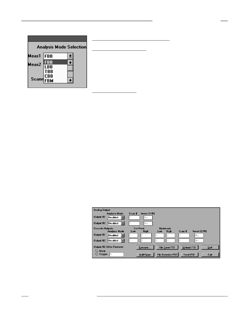
5.5.1 Analysis Mode Assignment
One or two
Measurement Analysis modes
may be programmed.
Meas1
or
Meas2
may be assigned to one or both outputs (Figure 5-8). If
ALL
is selected in either
Analysis mode, all of the scanning information is sent via the serial connection to a
host computer or PLC. The selection of
ALL
does not allow output assignments to be
made to that measurement mode.
The available
Analysis Modes
are listed on page 24 and described on page 28.
5.5.2 Output Programming
The controller offers 2, 3, or 16 outputs, depending on the model. One scan analysis
mode may be assigned to Output #1 and a second, different, analysis mode may be
assigned to Output #2. Programmable output response criteria are described in the
following sections.
All models except the 16-output models have an output labeled
Alarm
. This output
can be programmed to function as the alarm output for the controller’s self-diagnostic
circuitry, whenever a scan analysis mode is not assigned to it. The output may instead
be programmed to serve as a trigger input to begin the scan sequence of another
MINI-ARRAY System.
Models MAC-1, MACP-1, MACN-1, MACV-1, and MACI-1 — Discrete Outputs
The Output Assignments portion of the PSF Configuration screen, shown in
Figure 5-9, allows complete customization of response of the selected Analysis
Mode(s). With the exceptions noted, either Meas1 or Meas2 can be assigned to Output
#1 or Output #2.
Output #2
may be assigned as an Alarm output for the module’s self-diagnostic
circuitry whenever a scan analysis mode is not assigned to it. Output #2 can also be
programmed to serve as a Trigger input to begin the scan sequence of another MINI-
ARRAY System. The Trigger value is the beam location along the array at which the
Trigger output (during a scan) occurs.
Set Point (Low and High) determines where within the array the output(s) will
respond. In the case of total or contiguous beams made or broken, these settings
determine the minimum and maximum number of beams required for an output.
Figure 5-9. Output assignments portion of PSF Configuration screen
Figure 5-8. MINI-ARRAY Software Analysis
Mode Selection
Controller Configuration