4 connection of the detector block, Connection of the detector block, Figure 7 – Metrohm 761 SD Compact IC User Manual
Page 23: Position of the detector block 40
2.4 Connection of the detector block
761 SD Compact IC / Instructions for Use 8.
761.1043
15
2.4
Connection of the detector block
The metal-free detector block 1.732.0420 which must be fitted in the
instrument and connected belongs to the scope of delivery of the 761
SD Compact IC. Proceed as follows:
1 Note the cell constant
•
The cell constant c = XX.X /cm, measured at the works, is
printed on the rear side of the detector block. Note this value;
it must subsequently be entered in the software in order to
ensure that an exact display of the conductivity is obtained
(see Section 2.12.3).
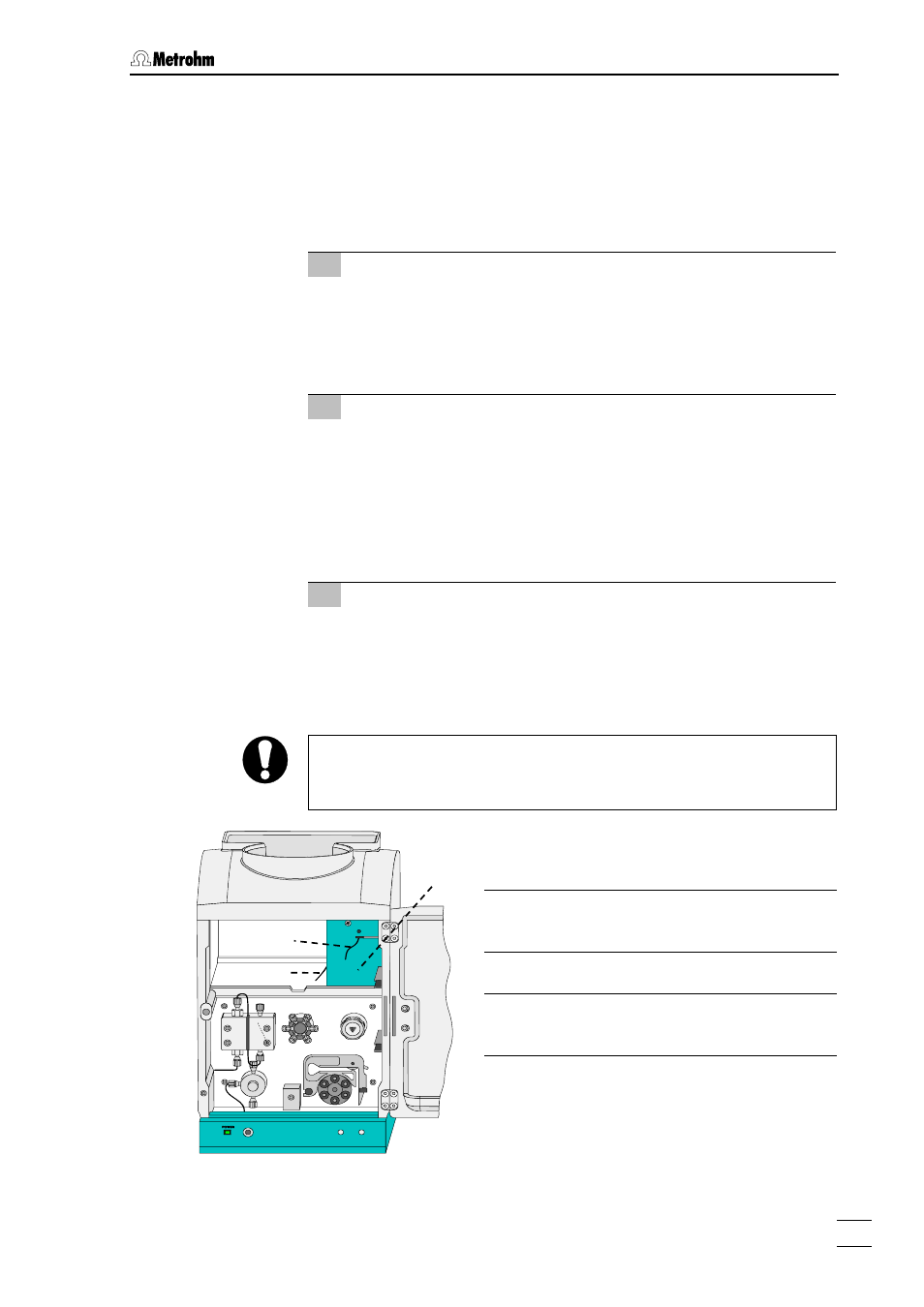
2 Install detector block
•
Unscrew the two upper knurled screws 11 from the upper
rear panel 12 of the 761 SD Compact IC, slacken the two
lower knurled screws 11 a little and remove the rear panel
•
Position the detector block 40 from the rear onto the space
provided in the 761 SD Compact IC and push it fully to the
front (see Figure 7).
3 Connect detector block
•
Pull the grey connecting cable permanently attached to the
detector block 40 out through the opening (where the upper
rear panel 12 previously was) on the rear of the 761 SD
Compact IC and plug it in to connection 20 "Detector Block"
of the 761 SD Compact IC.
Since other connections need to be routed through the rear openings
of the 761 SD Compact IC later on, you should not fit the rear panel
back on until the end of the installation procedure (see Section 2.10).
Figure 7:
Position of the detector block
Inlet capillary to detector block
PEEK capillary, permanently attached
Outlet capillary from detector block
PEEK capillary, permanently attached
40
39
41