Figure 18, Assembling the suppressor, Figure 18 ) to clean the connector – Metrohm 761 SD Compact IC User Manual
Page 109: Unscrew the nut 89 from, 90 and suppressor rotor 91 from, 90 from the suppressor rotor 91, 90 to, 90 (order number 6.28, R 91 using
6.2 Maintenance and servicing
761 SD Compact IC / Instructions for Use 8.
761.1043
101
5 Insert the suppressor rotor
•
Insert the suppressor rotor 91 into the suppressor holder 92 in
such a way that the tubing connections at the rear of the rotor
fit in the corresponding openings inside of the holder and that
one of the three holes in the rotor can be seen from below in
the opening in the holder.
•
If the rotor has been inserted correctly, its sealing surface will
be approx. 4 mm inside of the holder. If this is not the case,
move the rotor into the correct position from below with the aid
of a sharp object (e.g. screwdriver)
6 Clean the connector
•
Clean the sealing surface of the connector 90 using a lint-free
cloth and ethanol.
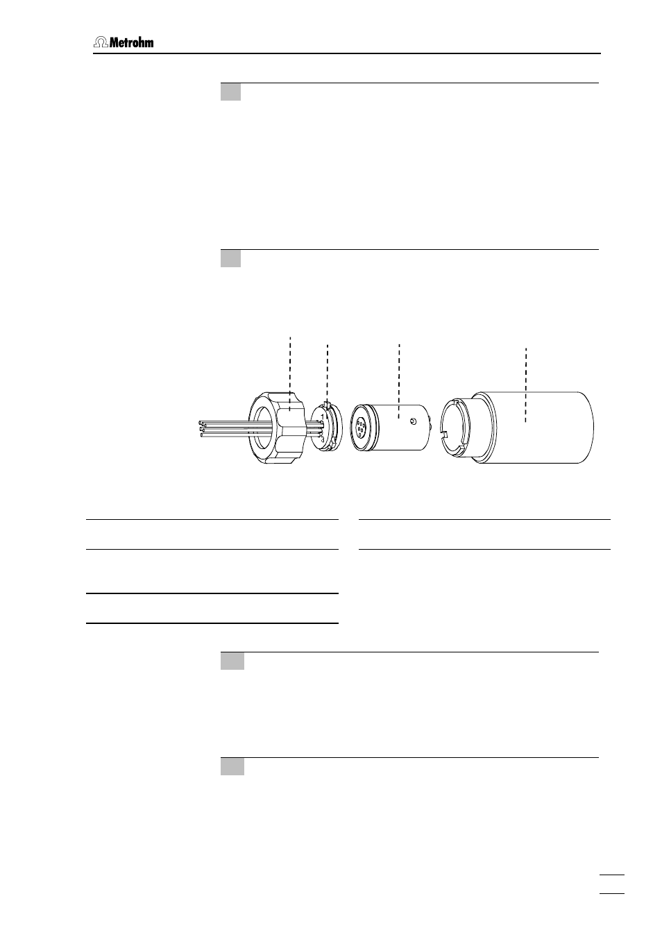
Figure 18: Assembling the suppressor
90 Connector 6.2832.010
with inlet and outlet capillaries
91 Suppressor rotor 6.2832.000
92 Suppressor holder
7 Insert the connector
•
Fit the connector 90 onto the suppressor holder 92 in such a
way that connection "1" is at the top and that the three lugs on
the connector fit in the corresponding openings of the holder.
•
Screw the nut 89 onto the thread of the suppressor holder 92
by hand (do not use tools).
8 Connect and condition the suppressor
•
Reconnect the suppressor to the IC system.
•
Before switching the suppressor to the next position, rinse all
three suppressor units with solution for 5 minutes.
89
90
91
92