Bowers Group Trimos Vectra Height Gauges User Manual
Page 5
750 50 0002 03
5
2.1 Instrument
construction
1. Column
2. Upper measuring insert holder
3. Screw for the adjustment of the floating probe suspension
4. Transport safety screw for locking of the probe suspension (chromium plated)
5. Screw for the measuring force adjustment
6. Lower measuring insert holder
7. Measuring
insert
8. Base with air cushion system for instrument displacement
9. Operating handle for the displacement of the instrument
10. Press button to activate the air cushion
11. Programmable function keys
12. Handwheel for measuring carriage displacement and probing movement (motorized version)
13. Display unit (see details here-after)
2.2 Handwheel for measuring carriage displacement and probing (manual version)
14. Handwheel for measuring carriage displacement and probing movement (manual version)
15. Locking device to activate the fine adjustment
16. Fine adjustment screw
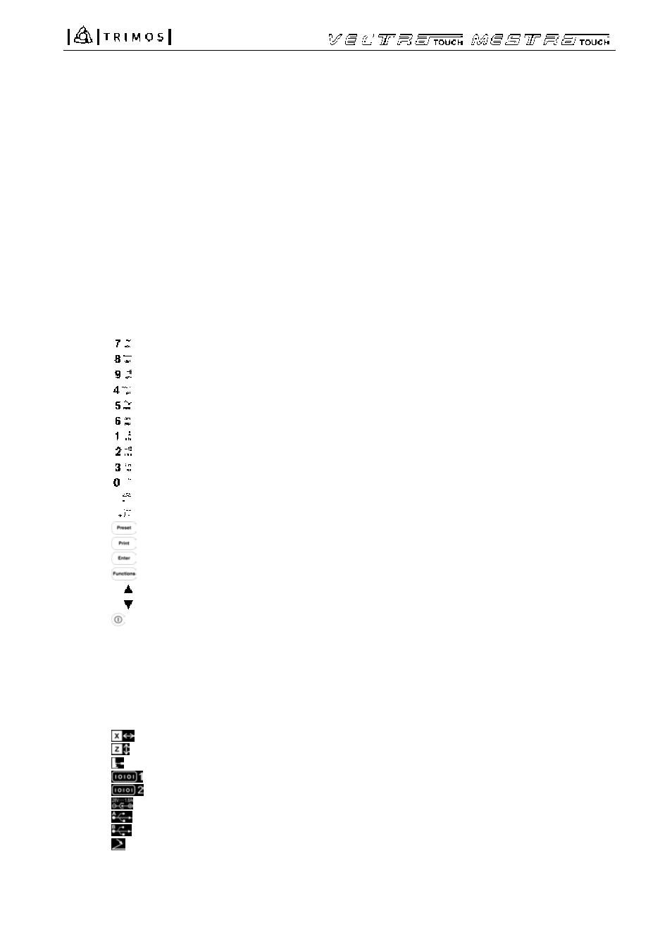
2.3 Display
unit
17.
Selection of references / numeric display of 7 / alphanumeric display of a b c
Selection of resolution / numeric display of 8 / alphanumeric display of d e f
Storage of probe constant / numeric display of 9 / alphanumeric display of g h i
Selection of measuring unit (mm/inch) / numeric display of 4 / alphanumeric display of j k l
Min, max or delta mode/ numeric display of 5 / alphanumeric display of m n o
Zero setting of the display / numeric display of 6 / alphanumeric display of p q r
Squareness deviation checking / numeric display of 1 / alphanumeric display of s t u
Angle measurements / numeric display of 2 / alphanumeric display of v w x
Selection of the calculation mode / numeric display of 3 / alphanumeric display of y z
Selection of the tolerance limits mode / numeric display of 0
Complete clearing of the buffer / decimal point display
Clears the last value stored in the buffer / change of sign
18.
Sets the display to the previously input preset value of the current reference
19.
Print-out of data
20.
Confirmation of selected or input data
21.
Selection of main functions
22.
Displacement of the cursor to the previous field
Displacement of the cursor to the following field
23.
On/Off key (power ON / OFF)
24. Probe setting direction indicator
25. Green light : measurement in specified tolerances
Red light : measurement out of specified tolerances
Orange light: measurement out of specified tolerance, but the part can be retouched.
26. Menu of functions
27. Display (touch screen for models Vectra-Touch and Mestra-Touch)
2.4 Interfaces/connectors
28.
X axis (electronic probe for checking of squareness deviation, horizontal)
29.
Z
axis(vertical)
30.
"Instrument"
connector
31.
RS 232 male
32.
RS 232 female
33.
AC adaptor connection
34.
USB
A
35.
USB
B
36.
Foot pedal connection