Bowers Group M&W Mechanical Depth Gauge 172 Series User Manual
Depth gauge instructions, Mechanical depth gauge 172 series
DEPTH GAUGE INSTRUCTIONS
Mechanical Depth Gauge 172 Series
Please carefully review these instructions to ensure proper and accurate use of your new Depth Gauge.
For more information visit
www.moore-and-wright.com
Partners in Precision
Operation
Zero Point Confirmation
• Setting zero for measurements 0-25mm. Place the depth base on a surface plate or flat surface. Loosen the bezel lock screw, adjust the dial
on the depth gauge to the "0" position and tighten the screw.
Measuring Procedure
• For measuring lengths greater than 25mm add the necessary amount of measuring rods for the depth required.
• To ensure correct measurements after adding additional rods, the dial depth gauge should be set against a master part or a setting master
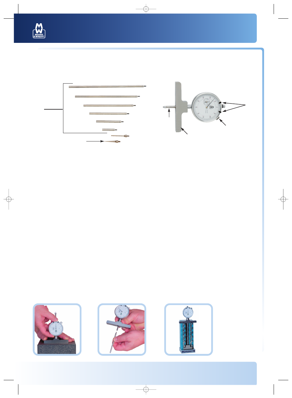
1: Tolerance markers
2: Bezel lock screw
3: Measuring base
4: Plunger
5: Extension rods 0-150mm
6: Spline point
7: Needle point
8: Ball point
Specification:
Indicator range: 0-25mm
Measuring range with extensions: 550mm
Graduations: 0.01mm
Zeroing the indicator
(without the extensions)
on a flat surface.
Installation of an
extension rod.
Zeroing the indicator
using an extension rod
and a setting master.
2
3
4
7
5
1
02_Manual_MW172-01 1/7/08 15:51 Page 1