Bowers Group Trimos Vectra Height Gauges User Manual
Page 21
750 50 0002 03
21
Acquisition in X
Perform all measurements in the same sequence than for Y.
The number of the bore (shaft) to be checked is indicated
below the current measurement value.
The acquisition ends automatically after the last bore (shaft)
has been measured. The coordinates of each bore (shaft)
and their diameter values (= mean value according to Y and
X) will be stored in the memory.
7.1.4 Processing of the results
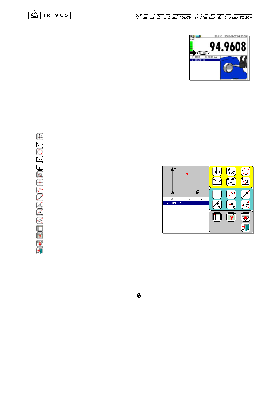
Display of 2D functions
a) Function
symbols
Transposition of the coordinate system
Alignment / rotation of the coordinate system
Calculation of the PCD
Cartesian coordinate system
Polar coordinate system
Back to the original coordinate system
Creation of a reference center point
Alignment of center points
Distance between 2 center points
Angle to 1 point, the origin and the X axes
Angle between 2 center points and the X axes
Angle between 3 center points
Table of measured values
Table of calculated values (required results)
Sends the calculated values to the buffer
Closes the 2D mode
b) Coordinate system position indicator :
The figure indicates the active coordinate system
(cartesian or polar). 3 fields allow to visualize the
numbers of the bore (shaft) related to the alignment of
the coordinate system. If the selected origin of the
coordinate system is a known point, it will be shown
above the X axes at the right side of the symbol .
c) Buffer:
Each measurement will be stored in the buffer. To avoid
an overload of the buffer, the list of the calculated points
will not be systematically renewed (see further on
"Transfer of the calculated values to the buffer").
a
b
c