Bowers Group M&W Digitronic Depth Gauge 172 Series User Manual
Depth gauge instructions, Digitronic depth gauge 172 series
For more information visit
www.moore-and-wright.com
Partners in Precision
DEPTH GAUGE INSTRUCTIONS
Digitronic Depth Gauge 172 Series
Please carefully review these instructions to ensure proper and accurate use of your new Digitronic Depth Gauge.
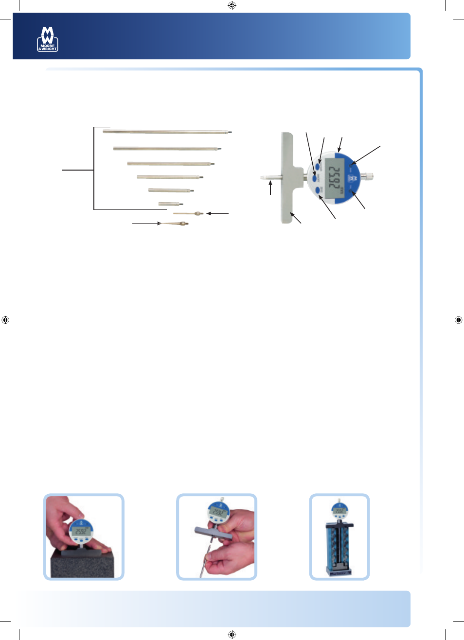
Features
1: ON/OFF
2: Direct mm-in conversion
3: Floating zero
4: Absolute/Incremental readings
5: Tolerance indicator
6: Battery cover
7: Measuring base
8: Plunger
9: Extension rods
1-6"/25-150mm
10: Spline point
11: Needle point
Specifications
Measuring range:
0-22"/0-558mm
Indicator range:
0-1.0"/25.0mm
Resolution: 0.0005"/0.01mm
Accuracy: ±0.001"/0.03mm
Repeatability: 0.0005"/0.01mm
Display:
LCD (11.0 mm high)
Maximum measuring speed:
1.5m per second
Battery:
3V, type CR2032 Lithium
Battery life:
Approx. 1 year
5
7
11
8
10
9
4
3
1
2
6
Zeroing the
indicator on
a flat surface.
(without the
extensions)
Installation of an
extension rod.
Zeroing the
indicator using
an extension rod
and a setting
master.
Operation
• To turn the indicator on or off press ON/OFF (1) momentarily
• For measurement between 0 and 1"/25mm. Place the depth base on a surface plate or other flat surface and press ZERO. Zero can also be set
at any point within its range in either ABS or INC
For measuring lengths greater than 1"/25mm. Add the necessary amount of measuring rods for the depth required. To ensure correct
measurements after adding additional rods, the depth gauge must be set against a master part or a setting master
• Press mm/in (2) to display readings in either inch or metric
• Press ABS/INC (4) to toggle between Absolute and Incremental reading. ZERO may be set at any location in either mode
• Tolerance indicators may be activated by pressing TOL (5) one time. "s" will appear in the display. Displace the spindle so the maximum
allowed reading is displayed and press TOL (5) once more. "t" will appear in the display. Displace the spindle so the minimum allowed
reading is displayed and press TOL (5) once more. "OK" will be shown in the display while your readings are between the two allowed
readings. Once either of these settings has been exceeded "OK" will flash indicating an out of tolerance measurement. To exit TOL (5) mode
depress ZERO (3). To reset tolerances depress TOL (5) and input the max and min readings
Maintenance
• Avoid contact with liquids and excessive humidity
• If the instrument requires cleaning, use only isopropyl alcohol and a soft cloth
• Battery is low when the display flashes. To replace the battery, use a small screwdriver to open the side battery compartment (6)
Uses 1 CR2032 battery
MW172-01D_Manual_A4.indd 1
10/05/2012 13:24