Audio connection pinouts, Analog audio, Digital audio – AJA FS2 Manual User Manual
Page 109: Analog audio digital audio
FS2 v2.1r1
www.aja.com
109
Figure 15. Typical GPI Input and Output Connections
Audio Connection Pinouts
Analog Audio
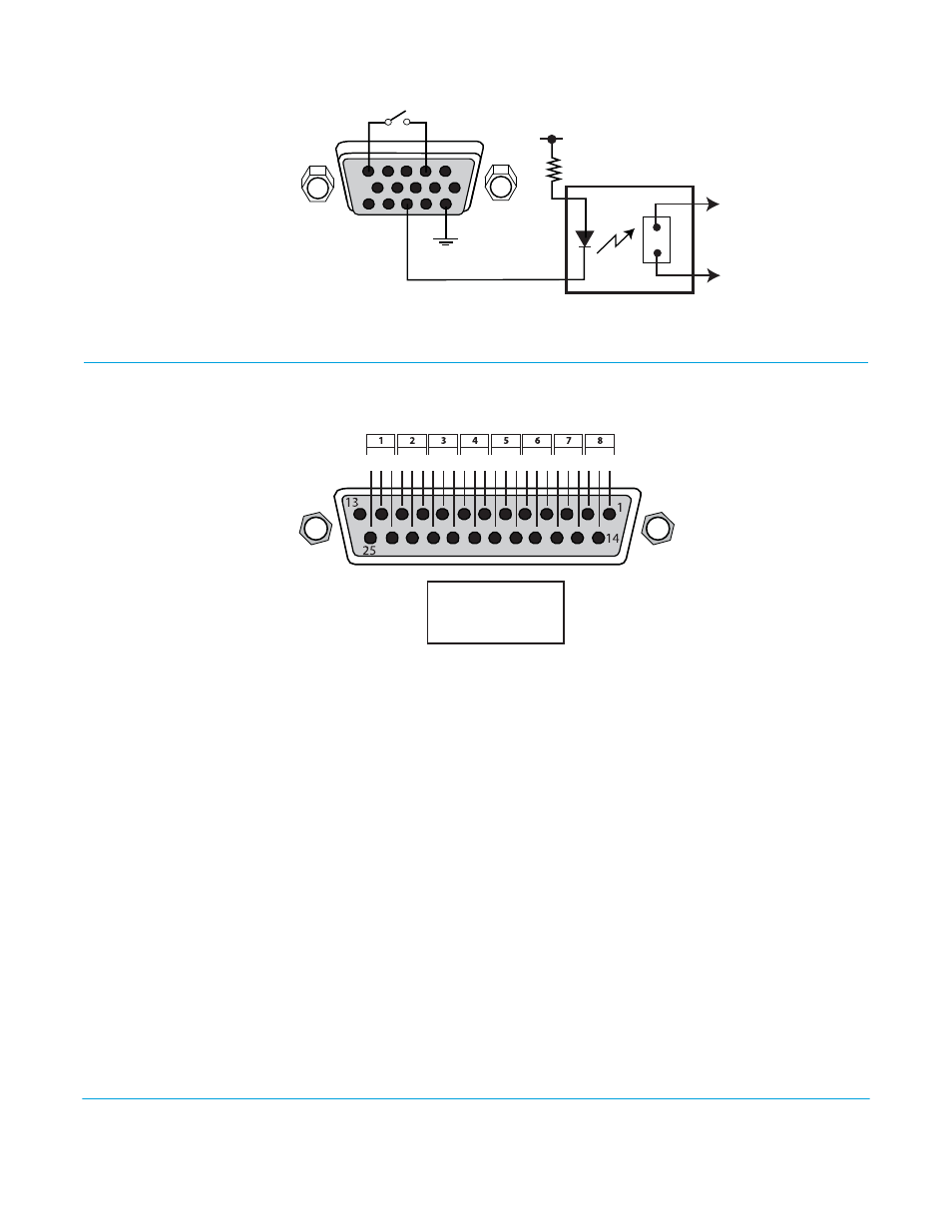
Figure 16. Audio Connector Pinout
The two DB25 connectors on the FS2 rear panel support a TASCAM-style cable snake for
balanced 8-channel analog audio. The pinout is the same for both input and output
connectors, each following the TASCAM DB-25 standard shown in the drawing above.
The top connector is for analog audio inputs 1-8, and the bottom connector is for analog
audio outputs 1-8
Digital Audio
The same pinout scheme as above is used for the AES/EBU digital audio connections,
except each channel handles a pair of digital audio signals (16 total per connector). The
top connector is for digital audio input channels 1-16, and the bottom connector is for
digital audio output channels 1-16.
1
15
11
5
6
10
GPI Out 4
GPI
In 1
+V
xmit+
xmit-
Optical Relay (SSR)
To Tally Lamp etc.
GPI GND 4
GPI
GND 1
G - +G - +G - +G - +G - +G - +G - +G - +
G = Ground
+/- = Balanced Pair
Key